by Jerry "SMMDigital" Conaway
| < Previous | Index | Next > |
| 238. Now we get to the really important business - control surfaces for the locomotive. We will start by making the handle for the Dynamic Brake, Throttle, and Reverser. Pull a cylinder onto the scene and give it dimensions that will match what you have on your locomotive. |  |
| 239. This handle will move side to side when dragged by the users mouse in the game. We need to place the pivot point for the handle on the end, so go to the bottom face, select it ("3", click on face), and run the "Shift Centre on Selection" plug-in. |  |
| 240. Drag another cylinder on scene, resize, and place it to make the hand grip for the control. |  |
| 241. From the Shape Operations Panel, run the "Taper" plug-in on the second cylinder. You may have to adjust the Percent field to get your taper just right. |  |
| 242. Use the Orientation field in the Properties and Information box to flip the handle. |  |
| 243. Run the Chamfer operation a couple of times on the end of the handle to round it off. |    |
| 244. Place the hand grip on the end of the main handle. |  |
| 245. After placing a finger guard at the handle-end of the grip, you can join all of these pieces into one handle (Select object, CTRL, select another object, click on "Shape Union" from the right-side Edit Toolbar). |  |
| 246. Move the object into the cab. While the handle is selected, you can use the Green Gizmo to the right of the screen to rotate the handle so you can get an idea of what it may do in the game. When you place it, put it in it's starting position. Please note that all of the objects that we are creating as control surfaces will later be animated, and therefore need to be kept in a group by themselves. If you know what the object will be called in the game, you can go ahead and name that Group and object. If not, we will wait until we start animating them to name them. |  |
| 247. Duplicate the handle we just created for placement on the Throttle and Reverser. |  |
| 247. Creations of the handles for the Train and Independent Brakes will not be shown, simply because I forgot to take photos while they were being created. Basically, they are shapes and cylinders, with a few Extrusions and Chamfering that we should, by now, be well able to do. Their pivots and Groupings are the same as the handles we just created. |   |
| 248. As a shape, the Horn handle is a bit more complicated, but it is created and placed on the control stand in the same way as the other handles we just created. |        |
| 249. Run the "Shift Centre On Selection" plug-in on the back face so that the horn will pivot downwards when it is selected in the game. |  |
| 250. The small DPDT flip switches are created nearly the same as the DB, Throttle, and Reverser handles, only smaller. They will flip upwards in the game. |        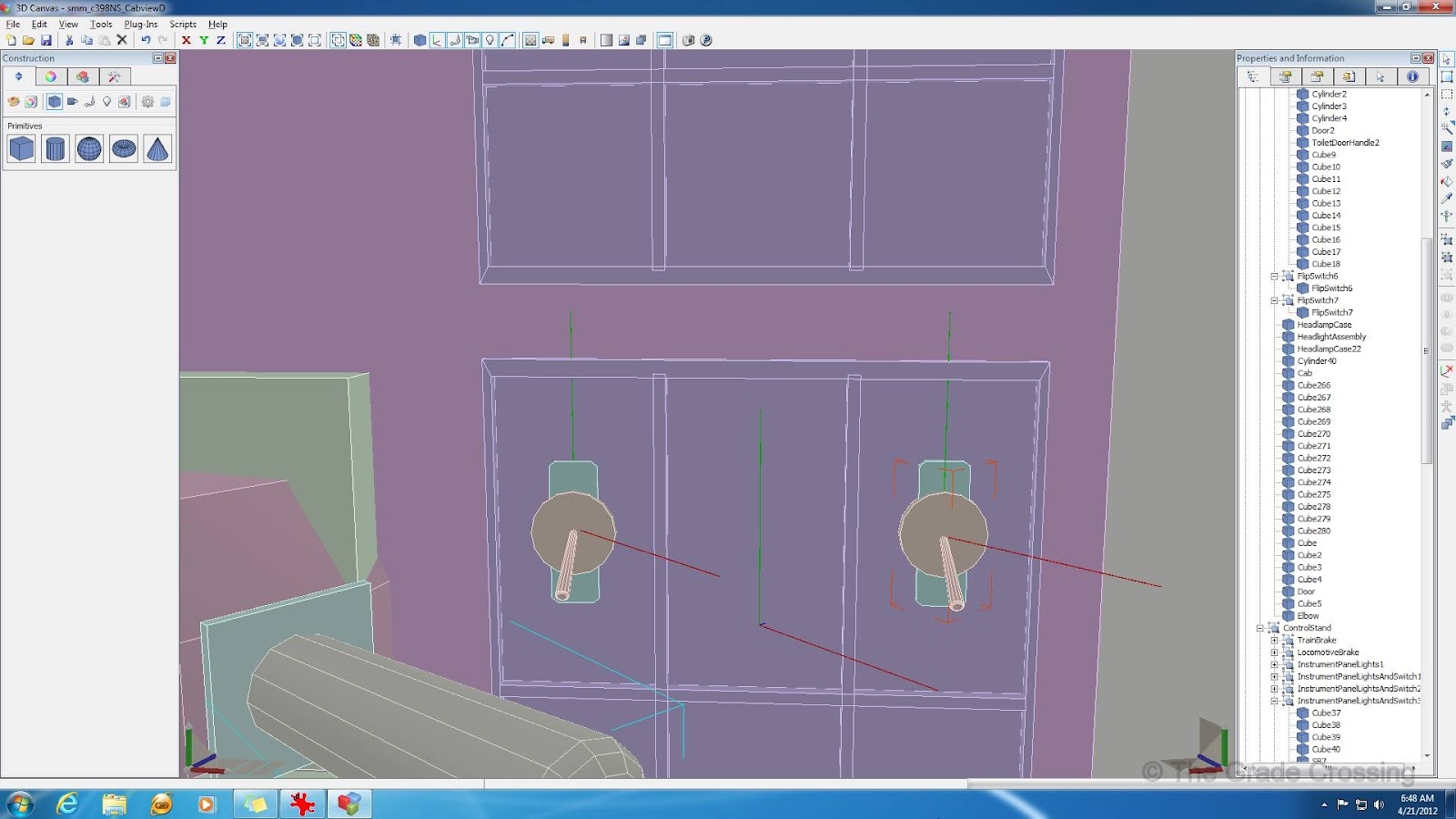 |
| 251. A couple of the controls, Lights in particular, take a turn-knob type of control. |        |
| 252. The needles on the instrument panel gauges are simple cylinders who's ends were Duplicated as a flat plane, and then two sides, on left, one right, were extruded. The rounded part of the needle is the pivot point (Shift Centre on Selection). |  |
| 253. Sander is a pull/push switch. It is made simply of cylinders that are shaped and tapered. |  |
| 254. Depending on your locomotive model, there may be additional controls that are not shown here, but on the one I'm building, these are the basics that it takes to drive in the game. |  |
| 255. Other non-control appliances inside the cab are simply a matter of detailing as was previously done on the outside of the locomotive. Again, details vary by model, so photos and measurements will give you the best chance of making a realistic looking unit. |        |
| All-in-all, we've done pretty well, adding detail and controls to the locomotive, but still keeping the poly counts down to less than 16,000. That will give us a little wiggle room if we need to add more control surfaces later. Now we will move on to the coupler. This small part of the locomotive causes some of the biggest problems when trying to get the locomotive in the game. The coupler that I'm about to build was made from reference drawings at Columbus Castings. I didn't exactly follow the drawings, but made them close enough to represent our couplers quite well. | |
| 256. Start your coupler by dragging a cube on the scene and resizing it according to the plans. |  |
| 257. As with our locomotive controls, we need the pivot point of the coupler to be on the end of the drawbar. Select the end of the drawbar nearest you and run the "Shift Centre on Selection" plug-in on it. |  |
| 258. Use the fields under the Properties and Information tab to put the coupler end exactly on coordinates x-0, y-0, z-0. If this is not done, the coupler will malfunction and possibly cause SoBHH's. |  |
| 259. Now we are going to extrude the other end of the coupler several times to get the basic shape of the coupler hand. |     |
| 260. Now we are going to Chamfer and push/pull on the resulting edges to sculpt the coupler. You should be relying heavily on the drawings to get the proper shape and size. |    |
| 261. Lock your Y and X axis and push the front face back to create the coupler pocket. |  |
| 262. More Chamfering to sculpt parts of the coupler. |  |
| 263. We need to clean up a few edges by selecting those lines ("2", select line) and using the Trim operation. |  |
| 264. Select lines and push/pull to do more sculpting. |   |
| < Previous | Index | Next > |
Published with permission from Jerry Conaway, 2012
No comments:
Post a Comment