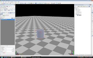
| 1. From the 3DC Construction Primitives panel, pull the shape of a Cylinder onto the board. Once you have placed it as close to the center of the scene as possible, use the shape operations tab and give it a Longitude of 20. This will give the cylinder 20 sides.
| 
|
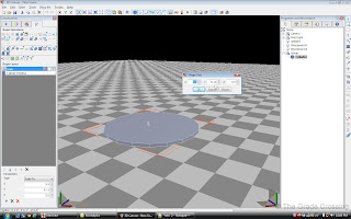
| 2. Now, right click on the flattened cylinder and choose "Scale" and "To Size". This locomotive wheel is 40 inches in diameter, with a 1" flange all the way round. So we will put 3.5 (3'6", or 42 inches) in the X and Y dimensions of the Scale box. We want the flange to be about 1" wide, so we will put .11 in the Y dimension box.
|  |
INFORMATION: AXIS. When the "Axis" is referred to, we are not talking about World War I. We are referring to Side-to-Side (X-Axis), Up-and-Down (Y-Axis), and Front-to-Back (Z-Axis). These movements may be different dependent upon the version of 3DC you are using.
|
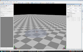
| 3. Under the "Properties and Information" box, click on the "Group" (the Folder icon) in the Scene Hierarchy then go to the "Components Properties" tab (third tab from left) and zero out all the values under the "Position" fields. This will place our flange at exactly the center of the scene.
|  |
INFORMATION: GROUP. A group consists of a selection of objects all bound together. They move as one when selected in the Scene. The Group itself looks like a folder or directory. Groups can have sub-groups, and can also have LOD designations. For example "1_0050_Groupname" would mean that all objects within that folder/directory, or Group, would be visible in the game out to 50 meters.
|
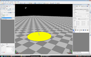
| 4. Select the top face of the flange cylinder by holding down the "3" numeric key and clicking on that face. Once it turns yellow, go to the Primary Toolbar at the top of the window, and from the "Plug-Ins" menu, select "Shift Centre on Selection". This will make the top of the flange the center of our wheel, for now.
|  |
| 5. Drag another cylinder from the "Construction" panel onto our flange cylinder. Then once again in the Scene Hierarchy select the Group the cylinder is in, click on the "Components Properties" tab, and zero out ONLY the X and Z fields. This will place this cylinder in the center of our scene.
| 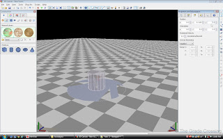 |
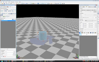
| 6. Click on this new cylinder, and in the "Shape Operations" tab of the "Construction" panel, give the cylinder a Longitude of 20.
|  |
WARNING: CYLINDERS ARE POLYGON KILLERS. Their multiple faces will drive the polygon count of a model through the roof in short order. The only reason that we are using so many faces on the wheels of this model are that I like my wheels to be as round as possible. For all other applications, the longitude (number of faces) of any cylinder will be kept at 10 or below.
|
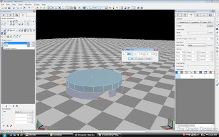
| 7. Right click on this cylinder, choose "Scale", "To Size", and enter the values you need for your wheel. This wheel is 40" in diameter (3' 4", or 3.33) so that is what we will enter in out X and Z values. The wheel is horizontaly 4" thick, so we will enter .33 for our Y value.
|  |
| 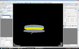 |
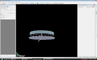
| 8. Rotate your view so that you can see the underside of the wheel. Select the underside of the wheel face by holding down the "3" numeric key and clicking on that face. Now press the "Delete" key. The reason we have done this is because this face will never be seen in the game, so it is unnecessary. We can delete any faces like this so that we can save polys for other areas.
|  |
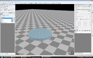
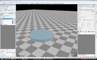
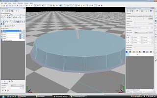
| 9. Click on the wheel again, go to the "Shape Operations" tab under the "Construction Panel" and click on the "Taper Shape" button. Then, go down to the "Parameters" "Control" field and enter "95". This will taper the wheel edge. On the prototype, this taper helps the locomotive navigate curves by making the diameter of the wheel on the outer side of the curve larger, and the diameter of the wheel on the inner side of the curve smaller.
|  |
|  |
|  |
| 10. Drag the wheel down until is makes contact with the top of the flange. Select both shapes by clicking on the flange, then holding down CTRL and clicking on the wheel. From the right side "Edit Tool Bar", click on "Shape Merge". This will make our wheel one piece.
| 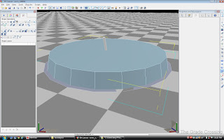 |
| 11. Go back to the Scene Hierarchy tab and click on the group that our flanged wheel is located in. Go back over to the "Components Properties" tab and put a value of "-90" in the Z-Orientation field, and a value of "0" in the Y-Position field.
| 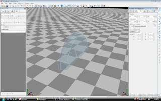 |
| 12. Select the wheel-side of the flange by holding down the "3" numeric key and clicking on the face. In the "Primary Toolbar" at the top of the window, select "Plug-Ins" and "Shift Centre on Selection". This will put the center of the flange in the center of the world, which is vital for positioning our wheel.
| 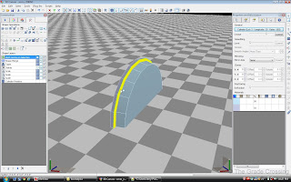 |
| 13. Under the Scene Hierarchy click on the Group our wheel belongs to, then under "Position" field in the "Components Properties" tab, input "2.355" into the X-field. This will move the wheel horizontally out from the center.
| 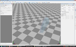 |
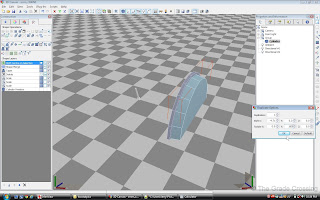
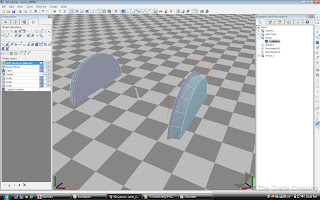
| 14. Now click on our wheel to select it. In the right side "Edit Tool Bar", click on the "Duplicate Button" to bring up the "Duplicate Options" box. In the box, input "-4.71" in the X-Shift field, and "180" in the Y-Rotate field. Click ok, then left-click on the duplicate button. After this operation, you should see two wheels, spaced at a distance of 4' 8-1/2" from each other from outer flange to outer flange.
|  |
|  |
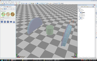
| 15. From the Construction Primitives panel, drag a cylinder onto the center of the scene. As we have done before, click on it's Group, and in the "Component Properties" fields, zero out all fields under positions. Give it a value of "90" in the Z-Orientation field.
|  |
| 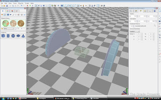 |
| 16. Scale the cylinder ("Scale" "To Size") to X-.75 Y-7.33 Z-.75. This will give us an axle that is 9 inches in diameter by 7' 4" long.
| 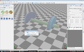 |
| 17. Select the axle by clicking on it, then select one of the wheels by holding down CTRL and clicking on it. In the right side Edit Tool Bar, click on the "Shape Merge" button. After this, do the same for the other wheel. Your first set of wheels and axles is complete.
| 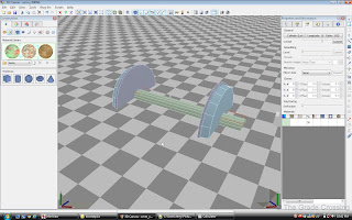 |
| 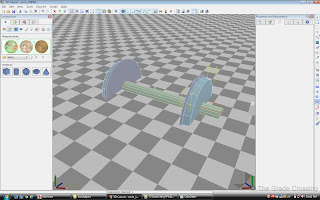 |
| 18. Lock down your X and Y moves by clicking on their respective buttons in the Primary Toolbar. This will allow you to move objects only in an up-down motion. Drag the newly created wheelset up until the bottom of the wheel, not the flange, is sitting on the "ground" in the 3DC scene grid.
| 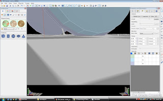 |
INFORMATION: LOCK AXIS. In the Primary Toolbar are three buttons: X, Y, and Z. These are for locking the axis of an object. For example, if you want to pull the face of an object forward (Z-Axis), but you have an unsteady hand and the face keeps drifting left (X-Axis), pressing the "X" button before beginning the operation will ensure that the face does not move side-to-side while you are pulling it.
| |
19. We need to take a moment to make sure that everything on our axle is pointing in the right direction to be used in Railworks. From the "Plug-Ins" menu in the Primary Toolbar, choose "Normalize Groups".
| |
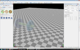
| 20. This wheel will compose the center axle of a three axle bogie. We know from the information we have about this locomotive that the center axle on the truck is 21' 7" from the center of the locomotive. So, we are going move this wheel 21.67 feet to the FRONT of the scene by selecting it's group and putting that value in the Z-Position field under the "Components Properties tab.
|  |
| 21. Now, we also know that center axle on the rear truck is 43' 4" from the center axle on the front truck. Right click on the "Duplicate" button on the right side Edit Toolbar to open the "Duplicate Options" box. Plug the value "43.33" in the Z-Shift field. Click OK, then left click on the Duplicate button.
| 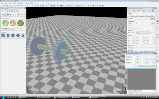 |
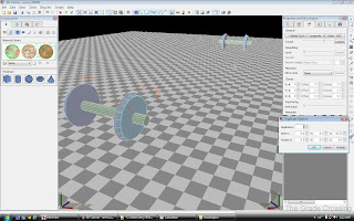
| 22. You now have the rear center axle (closest in the photo) and the front center axle (farthest away). The reason this is oriented this way is that it needs to be or the locomotive will place ass-backwards in the game (it may also cause you some problems in getting the loco into the blueprints).
|  |
PRO TIP: DUPLICATION. It is much easier to build a model that has lots of duplication involved if you have your textures ready beforehand. That way, you can texture the first part, then duplicate it as many times as you need as a finished part. Since texture creation will not be covered until later, this is not possible with this tutorial.
| |
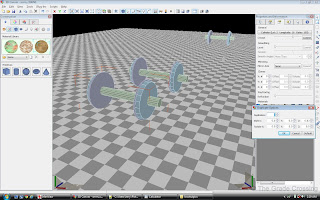
| 23. We need to duplicate the axles for the rear truck. The wheelbase (distance from the front axle to the back) for this truck is 13' 7". We are going to duplicate the front and rear axles for this truck from the center axle, so we need to divide 13.665 by 2 in order to get the distance we need to duplicate the axle. And that number would be 6.8325. Plug this number into Z-Shift field of the "Duplicate Options" box, click ok, then Duplicate the axle. This is our rear axle on truck 2.
|  |
| 24. Now do the same for the front truck, except this time put -6.8325 into the Z-Shift field.
| 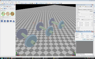 |
| 25. Follow the same procedure for the front truck axles.
| 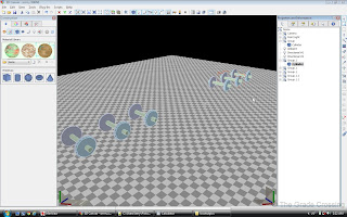 |
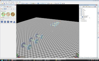
26. Now that we have all six axles in the scene, we are going to name them. Naming conventions are VERY important, because if you screw it up, the wheels will not turn, and it's very possible the locomotive will cause an SBHH. Starting with the very front wheel, name the GROUP that contains it, not the part itself, as follows:
1_0100_bo01wh01
This will tell the game that this is the first axle on the first truck of the locomotive. The rest of the axle Groups are named as follows:
1_0100_bo01wh02
1_0100_bo01wh03


1_0100_bo02wh01
1_0100_bo02wh02
1_0100_bo02wh03
| 
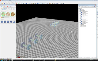 |
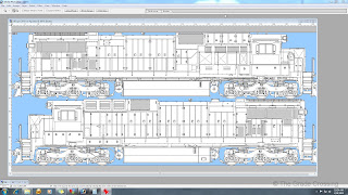
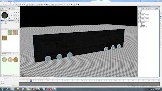
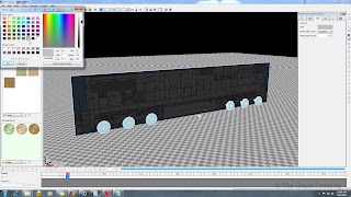
| 27. The next step is to make the template for your locomotive. Assuming you already have your locomotive drawing/diagram, you need to make a texture out of it. Open your texture modeling program and make a new texture, 1024x1024. Select the JPG of your locomotive drawing and paste it into the texture, resizing it to fit. If you have the other side of the locomotive, then paste it on the bottom. Save it as a .BMP file in the same folder as your locomotive. In 3DC, make a box that has the overall dimensions (overall length and height) as your locomotive. Then, under "Construction/Material Pallet", click on the folder icon, choose your locomotive template texture, select the area of the texture you want to use, and the paint both sides of the template block box with it. Position the box at absolute 0 - X-0, Y-0. With any luck, the wheels we have already made with match up with those on the template. If not, we will take the actual measurements we have over the drawing and just use the template as a loose guide for our loco.
Just as an aside for a better template fit to match up your wheels, do not include the bottom of the wheel flange or the couplers in the template. Include from the top of the hood to the bottom of the angle wheel (which is sitting on the "floor" of the scene , and from the tip of the rear snow plow to the tip of the front snow plow.
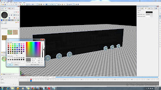
After painting your box template, you may need to lighten up your scene a bit. Do this by clicking on the "Ambient" light bulb in the Scene Hierarchy then lighten up the color with the Component Properties tab. Don't lighten it too much or your draw lines will wash out and the parts will be hard to see.
| 
 |
| 28. Now we get down to the nitty gritty. We are going to make the frame for the rear bogie. As Michael Vinci or that DeAngelo dude says, "the Sculpture is already there, I just have to free it from the marble". It's the same principle for oddly shaped parts such as this. We will be doing a lot of dividing, pushing, and pulling to bring the truck frame out of this part. The first thing to do is reshape a cube into the rough shape of the bogie frame.
| 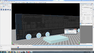 |
| 29. Next, we use "Component Properties" field to place the box on the X-0 position in the scene. Use the same position as your center axle in the Z-Position field, in this case -21.67, to position your bogie frame. Write down this number somewhere as you will need it later in the locomotive blueprint. Unlock Y and move it until the bottom of the box is the same height as the bottom of the truck frame.
| 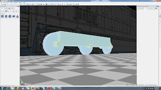 |
| 30. To get our bogie frame to the correct length, we are going to pull the end faces to match the ends of our drawing. After locking your X and Y axis, select an end by pressing the "3" numeric key, clicking on the face you want to move, then pull it to the end of the drawing. Do the same for the other end.
| 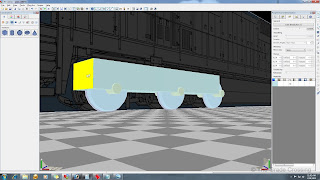
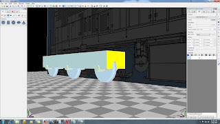 |
| 31. We are going to contour our bogie frame to fit. This will require a lot of face division, pushing and pulling. We will start by making one division line. Press the numeric "3" key to select the top face, then left click, and select "Divide". This will divide the top face into four sections. We only want two sections though, with the dividing line running across the X-Axis, so we will go to the "Shape Properties" tab in the Construction panel, click on the bogie frame, and from the Parameters field choose "Horizontal". You should see a line appear.
| 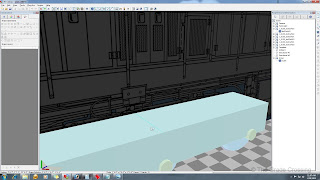 |
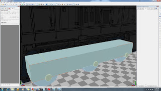
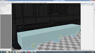
| 32. Now lock the X and Y axis, press the "2" numeric key, select the line and drag it to an area on the truck near where the shape of the frame changes. Now make more dividing lines in the same manner in the top of the frame so we can begin shaping. Now one oddity about 3DC is that when you are dividing a lot like this, sometimes you will have to alternate between "Horizontal" and "Vertical" lines. Practice a few times and you will see what I mean.
| 
 |
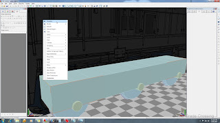
| 33. Let's chamfer the end of the truck to begin our shaping. Press the "2" numeric key and select the line on the top end of the frame. Right click and choose "Chamfer" from the menu. After you chamfer, lock the X and Y axis and drag the top edge line back to match the corner on the template. Then, lock the X and Z axis and drag the other chamfer line down to match the template.
| 
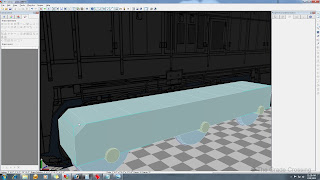 |
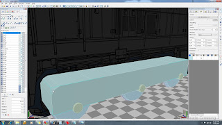
| 34. You'll notice that your template shows the frame as a little more rounded, so we will make another dividing line by selecting the face ("3" numeric, click), choosing "Divide" from the the right-click menu, and then entering "Horizontal" or "Vertical" in the Parameters box to get an X-axis line. Once you have the line, lock the Z-Axis and drag the line into it's desired position. Do the same for the other end of the truck frame.
| 
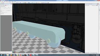 |
| 35. Now we can start pulling and pushing the edges we created earlier to sculpt the top side of the frame. Using the techniques we have already described, create a few more edges and push and pull them until the desired shape begins to form. Don't worry about smoothing just yet, as we will tackle that later.
| 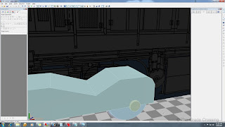 |
| 36. Just as we have done for the top of the frame, we need to divide the bottom face and move the resulting edges so we can push and pull the lines to make our desired shape. After you have your desired amount of edges, push and pull to sculpt your shape.
| 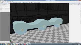
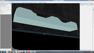 |
| 36. Just as we have done for the top of the frame, we need to divide the bottom face and move the resulting edges so we can push and pull the lines to make our desired shape. After you have your desired amount of edges, push and pull to sculpt your shape.
| 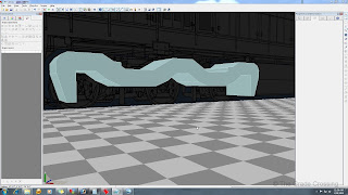 |
| 37. We have our rough frame shape. Now, if you desire, you may smooth it out a bit using the Chamfer tool. Simply press "2" numeric and click on an edge to select, then right-click and choose "Chamfer" from the menu. You can alter the amount of chamfering by clicking on the frame afterwards, and then from the "Construction" "Shape Operations" panel, choose a number to put in the "Parameters" field. You can choose from 1 to 50.
| 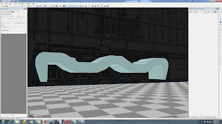 |
INFORMATION: Chamfering and smoothing adds polygons to your model, so it's a good idea to go sparingly if you are on a budget.
|
| 38. We've added a few more cubes, resized and centered them on the X-Axis, then divided, pushed, pulled, and chamfered to fit. With our wheels visible, it's beginning to look like a locomotive bogie.
| 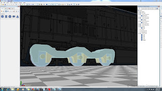 |
39. We need to go ahead and start grouping our bogie. Once again, naming is very important, and if you get it wrong, you might launch your locomotive into space when you try to couple to it. Find the group that the main frame is located in and name that group "1_0250_bo02" (remember we are working the back bogie first). After that, once you have sculpted and located all your sub parts, you can group them for LOD purposes and put them in this group.
| |
| 40. Next step, we need to hide the template and delete the faces on the bogies that we will not need. This will be all of the top and bottom, plus a few of the front and back faces. Select multiple faces by pressing "3" numeric and CTRL at the same time and clicking (or dragging) on each face to be deleted.
| 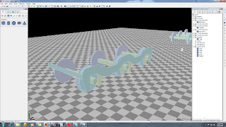 |
| 41. Click on the frame, then from the Main Toolbar, select "Plug-Ins" and "Double Side". Do this for the sub parts as well.
| 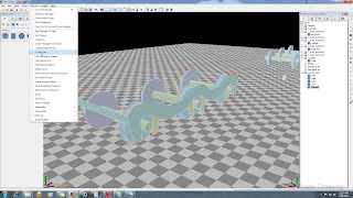 |
| 42. Select each interior face of the frame by pressing "3" numeric and CTRL at the same time. After selecting the faces, right-click and choose "Extrude Region" from the menu.
| 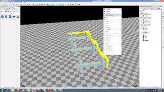 |
| 43. THis will give you a pretty funky looking frame. Correct this by checking "Extrude Using Face Direction" under the "Construction" "Shape Layers" box. Also, you need to fine tune the extrusion amount so that the frame almost touches the face of the wheels. Adjust the extrusion thickness in the "Extrusion" box.
| 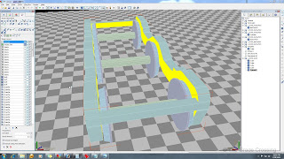 |
| 44. Now select and extrude the interior faces of the sub-parts, once again until they almost touch the wheels.
| 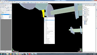 |
|
| 45. Now that our basic roughed frame is complete, we need to check the poly counts. Our budget for the bogies needs to max out around 3500 polys, so we'll do a quick check to see how much more we can do. Click anywhere in the "air" near the box and drag a blue box around the bogie to select all it's parts. Then, from the Main toolbar, select "Plug-Ins", "Information", and "Count Triangles". This particular bogie is already almost 1700 polys, so we will need to be cautious, and possibly draw some of the remaining parts, in order to save our frame rates!
| 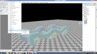 |


Where did you get the locomotive templates?
ReplyDeleteI get my templates from this site:
ReplyDeletehttp://trainiax.net/