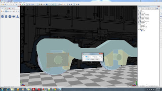
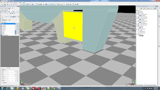
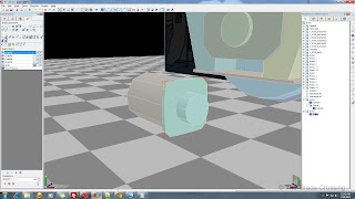
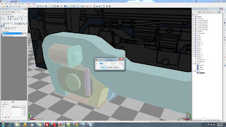
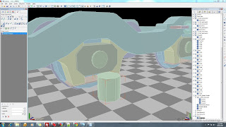
| 46. We've done our check, and we are halfway there on polys, so we will have to be creative, and may have to paint some details in. For right now, lets start making the journal boxes. Simply pull a cube onto the scene. We will place it and resize to fit. Then, we will chamfer the edges to get the desired shape. If the shape still needs tweaking, you can lock Axis as needed and push/pull the edges to fit.
| 
 |
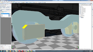
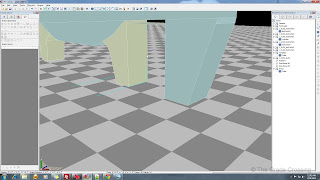
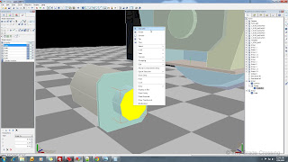
| 47. We want to delete any faces that will not be seen in the game to save polys, so select the back face and delete it (numeric key "3", click on face, "Delete").
| 
 |
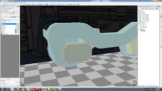
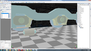
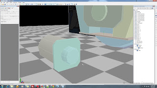
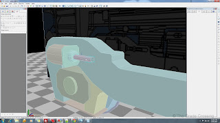
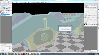
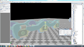
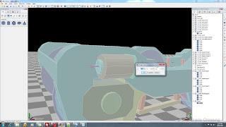
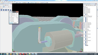
| 48. Now we need journal boxes on the other end of the axle. We can find the position of this box by clicking on it's group in the Scene Hierarchy then checking the "Position" fields in the Properties and Information panel. We need the X-Position value, which here is 3.1844.
|  |
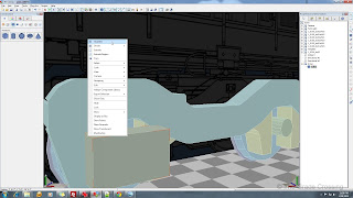
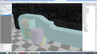
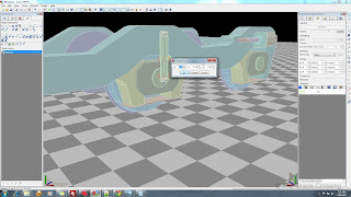
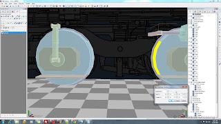
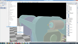
| 49. Click on the journal box, then in the right side Edit Toolbar, right-click on the "Duplication" button to bring up the Options menu. In the X-Shift field, we need to plug in a value that is twice it's current position, and we need it to go away from the camera, so we will put in a negative value: -6.3688. We also need to rotate the part 180 degrees, so we put that number into the Y-Rotate field.
|  |
|
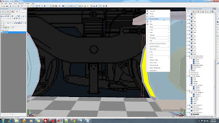
After you have set your values, click on the journal box, then the Duplicate button and we get a journal box on the other side of the bogie. Review this technique, because we will be using it quite often.
| |
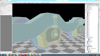
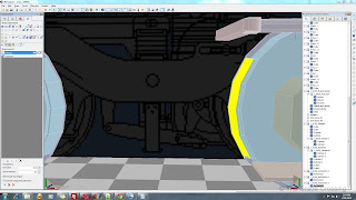
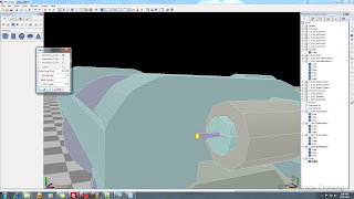
| 50. Back to the other side of the bogie, we need to put journal boxes on the other two axles. We already know that these axles are 6.8325' apart, so that is the value we will plug into Z-Shift field in the Duplicate Options box. We also need two Duplicates. Close the box, click the part, and click Duplicate. Now we have journal boxes on all our axles. Go and do the same for the other side of the bogie. |
 |
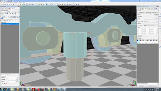
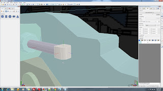
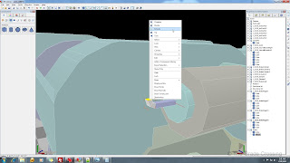
| 51. One of the more noticeable (and poly hungry) details of this locomotive's bogie are the brake cylinders. We'll start out by using a 9-sided cylinder, just like the one on the default ES44. Drag the cylinder on the scene, then use the Shape Operations tab to give it a longitude of 9. Then resize it to X-.75 Y-1.0 Z-.75.
| 
 |
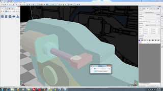
| 52. Now drag another cylinder onto the end of this one. Give it the same number of longitude (sides), and resize it to X-.41 Y-1.33 Z-.41. Select it's group in the Scene Hierarchy, then use the Component Properties tab to zero the X,Z coordinates, and drag it down onto the first cylinder until only about an inch is sticking out of the "up" end.
| 
 |
| 53. Go into the Scene Hierarchy and select the parent group that contains both cylinders. Go back into the "Component Properties" tab and enter -90 in the Z-Rotate field to turn the cylinder onto it's side. Now drag a cube onto the scene and resize it so that it will make what looks like a square joint between the bottom and top half of the brake cylinder. Chamfer the edges to give a little more of a rounded appearance.
| 
 |
| 54. The cylinder doesn't quite look right, so against my better judgement, I'm going to chamfer the top of the cylinder to round it off a bit. Off course, this will add polygons to the model. Do a "bulk chamfer" by selecting the entire top face then select "Chamfer".
| 
 |
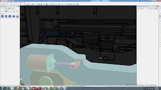
| 55. I've grouped all of the pieces of this brake cylinder together and moved it into position. Now we need a rod or two to tie it into the brake rigging. Again, drag a cylinder down onto the scene. Because this is going to be a smaller, less scrutinized part, I'm going to give this actuator rod a longitude (Sides) of 8. Then resize to X-.18 Y-1.33 Z-.18. Delete one face on the the end that will go into the main cylinder and thus will not seen. Use the "Component Properties" tab to Z-Rotate the cylinder -90 degrees before inserting it into the brake cylinder. You can delete the end face of the rod as well.
| 
|
| 56. Drag a cube onto the new actuator rod. Resize it to X-.20 Y-.18 Z-.20. Once you have positioned it on the end of the actuator rod, chamfer the front corners, then delete all the side faces except the back one that ties to the rod. Click on what is left, and from the Main Toolbar, select "Plug-Ins", "Double Side".
| 
 |
| 57. Drag another cube onto the socket we just made. Resize it to X-.1 Y-.15 Z-.23. Now, click on the object, then drag on the green gizmo in the lower right corner to rotate it just a bit. Finish our newly-cast tie-rod with a little Chamfer on the end.
In reality, the joint plate between the top and body of the brake cylinder has nuts and bolts. Instead of wasting more polys, we will simulate that with Normal Maps, later.
| 
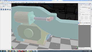 |
| 58. We can go ahead and group all of our brake cylinder parts together before we begin the duplication process. I have the LOD set on the main cylinder at 100 meters, as it's pretty large and I don't want to see it popping in and out of the picture. The smaller parts can have a closer LOD value. If you are happy with your brake cylinder, you might want to consider joining all the parts together to make duplication easier.
|  |
| 59. I simply duplicated this cylinder and flipped it 180 degrees on it's X-Axis. I had to do a bit of fine tuning to get it into position. Do this for the other side of the bogie as well. One very important thing to remember is that all Parts AND Groups must have unique names. There is a plug-in that you can run to rename all shapes in bulk, but Group names have to be done manually. If you have two Group names that are the same, the model will export, but it will not show up in the game.
|  |
| 60. Now we need a Damper for the middle axle. We'll start out with some cylinders and resize to fit. Basically, we will be duplicating and resizing to get the desired shape. For the hangers on each end, simply place a box that has top, bottom, and front side faces deleted and is then Double-Sided. Once you are finished, group everything up and rename if desired.
| 

|
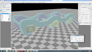
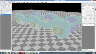
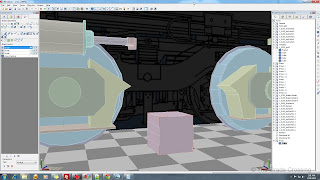
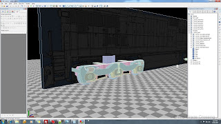
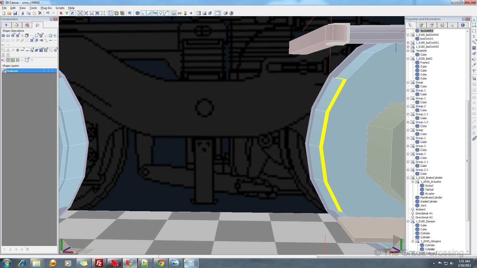
| 61. At 2600 polygons, we are quickly approaching our budget for this truck. We need to put on a few more important parts, like brake rigging. We'll start off with brake pads themselves. Select the faces of the wheel where the brake pad is located. Then, under the Duplication Options, put in the values that will allow you to duplicate those faces at about 1/2" distance from the wheel.
|  |
| 62. After you have copied the faces, select them again by right clicking, then choose "Extrude Region" from the menu. After the extrusion, use the "Parameters" field under the Shape Operations tab to give the brake pads a 1/2" thickness.
| 
 |
| 63. Now we need a cube, and once we have dragged one into the scene, we will divide the face that will be welded to the brake pad into four faces. Once we have done that, we place the cube and drag, push, and pull our edges until we get a shape that will roughly mold to the brake pad.
|  |
| 64. We mold the part to the brake pad by locking the X-Axis and dragging the edge lines. Afterwards, we delete the interior faces that will not be seen and resize the shape to fit. A little chamfering helps to round things out. Duplicate the part and place it on each brake pad.
| 
 |
| 65. Let's put in a few bars to tie it all together and fill out the bogie just a bit more. These are basically all just resized cubes that will be painted with details. They are duplicated x4.
|  |
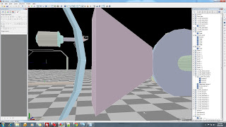
| 66. We'll make the tie bar between the two brake cylinders next. In the past I've done this by extruding a cylinder. But since we are on a budget, we will do it with a box shape. Drag a box onto the scene and resize to X-.05 Y-.05 Z-0.5
|  |
| 67. Select the end of the bar, and from the Plug-Ins menu, select "Shape Builder", "Piper". Once the plug-in field menu pops up, plug in the values that are shown and hit OK.
| 
 |
| 68. Once your first elbow has been extruded, click and choose the top face of it, then right-click and choose "Extrude". The default 6" value will do fine.
|  |
| 69. Select the top face of the extrusion and make another elbow in the same manner as described before.
|  |
| 70. Select the front face of the new elbow and extrude another section that is long enough to reach and go just past the next brake cylinder. Once you are there, make another elbow, extrude 6", another elbow, and extrude again until your pipe connects the two brake cylinders.
|  |
| 71. Now we are going to join all of the parts we just extruded into one piece. Select two pieces by holding down the CTRL key and clicking them. Then, in the right Edit Toolbar menu, click on "Shape Merge". Do this until all of the parts we just made are one piece. After you have finished that operation, copy the part over to the other side of the bogie.
|  |
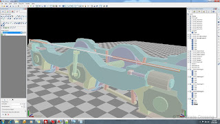
| 72. We need to lean the new part back up against the bogie frame, so we will click on the piece and grab the blue gizmo in the lower right corner of the screen. Drag the gizmo and the part will rotate on it's axis.
|  |
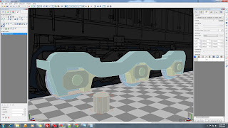
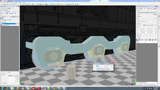
| 73. Really all that is left to do now with this bogie is a little filler material. The traction motors usually can't be seen, so I basically made a chamfered box in the middle of the truck that keeps it from being see-through. The pivot connector is an octagon with the ends deleted. This is another part that is usually not seen. The parts have all been grouped together under the second bogie.
|  |
| 74. Now it's time for the PIA part - duplicating the first bogie. We know that the bogie we just finished is at coordinates -21.67. So the new bogie (what will be the first bogie at the front of the loco) needs to be at coordinate 21.67. So, we add the two together to get 43.34. We want to duplicate just the truck frame first, so select all of the "loose" parts that aren't grouped under Bo02.
|  |
| 75. Right click on the Duplicate button to open the Duplicate Options box. Put in the coordinates of the new bogie into the Z-Shift field. Click OK, then duplicate the parts.
|  |
| 76. After checking to be sure everything is where it's supposed to be, we rename the new group "1_0500_Bo01". We need to make sure it is in the correct position, so open the "Component Properties" and check the Z-axis. It should read that the center of the bogie group is 21.67. If this checks out, then proceed to duplicate all of the other bogie parts. Remember to avoid confusion later on, rename your groups as you duplicate them. Usually the addition of a simple number at the end of the group will be enough to differentiate it from other groups.
| 
|
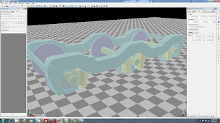
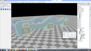
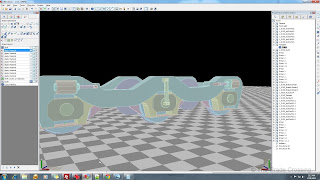
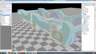
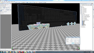
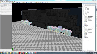
| 77. Now we are going to perform an operation that must be error free in order for the locomotive to work properly. One by one, choose the Group that contains each wheel and assign it to it's proper bogie. Your bogies and wheels should look like the example in the photo when you are done.
| 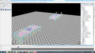 |
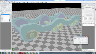
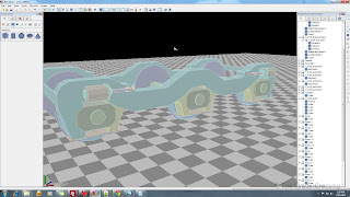
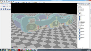
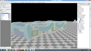
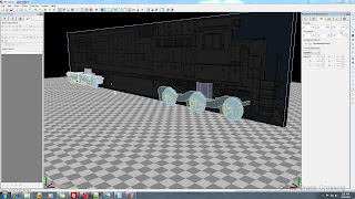
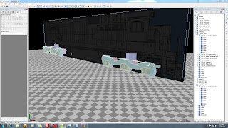
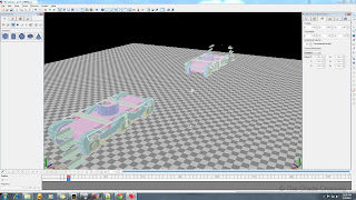
| 78. We need to gather the location information of the Bogie and each wheel contained within. This information will be plugged into the Bogie Blueprint in order to tell the game what parts to render as rolling wheels. First, click on Group 1_0500_Bo01, then under the "Component Properties" tab, check it's Z-Position field. Here, it is 21.67. Write that down or transfer it to a computer text editor or excel sheet for later use. Now click on each group that contains a wheel and write down the number in the Z-Position field. Save this information as well.
|  |


No comments:
Post a Comment