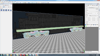
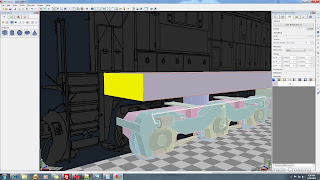
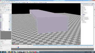
| 79. To begin work on the underside of the locomotive, I make a box that is the length of the locomotive, and six feet wide. In real life, this would simulate the frame rails that the deck is welded to. It helps give an idea of how things are set up above the bogies.
| 
|
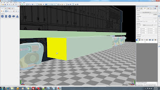
| 80. I'm going to put in the fuel tank now. Pull a box out onto scene floor, and resize it. Most modern diesels are 10' wide, so we will resize it's width to that, then push and pull the ends (Lock Z axis, numeric key "3", select face, pull/push) to get the proper fuel tank length. After we get the proper size, we chamfer the bottom edge of the tank, then push/pull the resulting edges along the X-Y axis to get the shaping right.
|  |
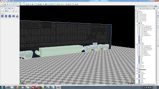
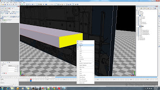
| 81. The air cylinders at the front and rear of the fuel tank are basic cylinders with half-spheres attached to them at each end. Make the cylinders as we have done before, then size a sphere to match the cylinder diameter and delete all of it's bottom faces. Flatten it using the Scale selection, then place it on the ends of the tank. We will worry about piping and other details later.
|  |
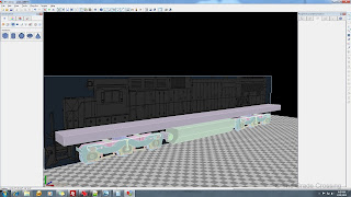
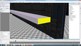
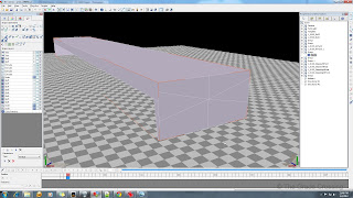
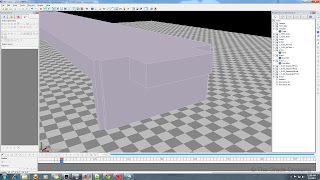
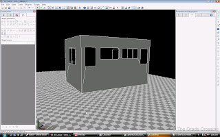
| 82. Pull a cube out onto the scene and size it both vertically and horizontally to fit the deck of the locomotive. You may have to adjust the deck by pushing and pulling on the face to fit the template.
| 
 |
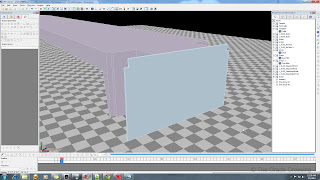
| 83. We want to extrude the front of the deck to match the template, so we will use a combination of extrusion and face-pulling to get the part the way we want it to look. When we are finished extruding the part, press the "2" numeric key to trim the unneeded edges from the part.
| 

 |
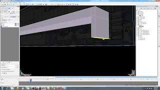
| 84. We need to divide this face into three parts so we can extrude another part, but we have a problem. Sometimes, when you have done a lot of cut or extrusion on an object, you start getting fractured faces when you try to divide a face on it. We will have to try another way.
|  |
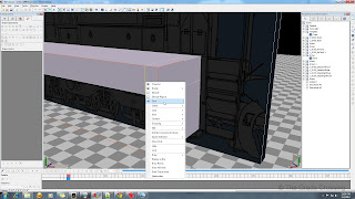
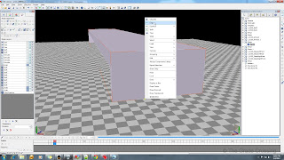
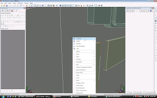
| 85. To divide this face, we will need to select the top edge of the face, press the "2" numeric key, right-click on the edge, select "Divide" from the menu, and select "3 edges". This will put two points on the top edge. Do the same thing for the bottom edge.
| 
 |
| 86. Now select the top point that is closest by holding down the "1" numeric key and clicking on the point. Hold down the CTRL key and click on the bottom point just below it. Both points should now be selected.
|  |
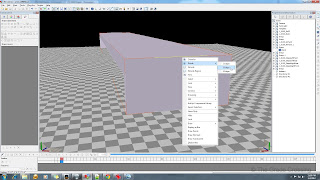
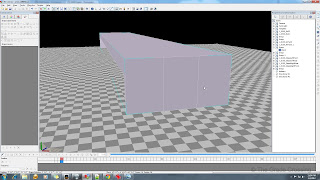
| 87. While still holding the CTRL key, right click on one of the points, and from the menu, choose "Edge". You should see a straight line appear between the points. This is our new edge. We need another one, so we are going to follow the same procedure for the top and bottom points on the other side of the face.
| 
 |
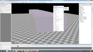
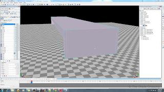
| 88. We need these edges to be close to the outside edges of our bulkhead, so we lock the "Y" and "Z" axis so we can't move the lines back or up, then press the "2" numeric key to select the line, then we will drag each line to the edge of the bulkhead. If you want to be sure that both lines are equidistant, check the Parameters field under the Shape Operations tab.
|  |
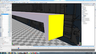
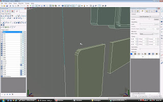
| 89. We now extrude an extension to the stepwell bulkhead.
|  |
| 90. Using the same method as above, we make another extension out to the locomotive pilot. Don't delete the front face on this extension. Even though it will be hidden by the Pilot, we may need it to make the anti-climber later on.
|  |
| 91. The Pilots are made from simple cubes, shaped to size. The notches that are cut in the top corners are Chamfered with an extra line added to them, then manipulated to create the notch. Once again, we are not going to add detail, such as snow plows and cables, until we are finished with the main body of the locomotive.
|  |
| 92. Our steps are pretty generic - a cube that has the front, top, and sides deleted, then the remaining part Double-Sided. To get the down-face in the front, extrude the bottom of the step, then delete the bottom of it. Run the double-side again. Duplicate as needed. The anti-slip cut-outs will be simulated with Alpha paint.
|  |
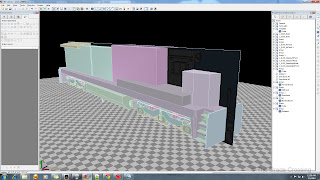
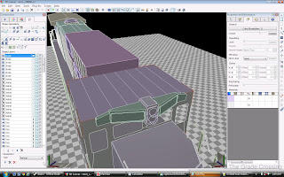
| 93. No we get to the fun part - rough blocking the actual locomotive hoods. Everything here is just a basic block, placed where it is supposed to go. I could have extruded everything from a single block, but that would provide little flexibility for later adjustments and painting.
|  |
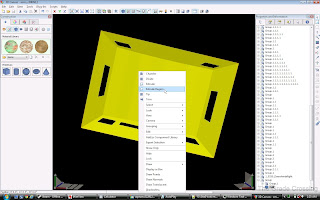
| 94. Doing the window cutouts for the cab is the hardest (and most dangerous) of things that you can do. The easiest way, the way shown here, is using the Boolean Subtraction. This method takes a shape, in this case a cube I chamfered to the shape of a window, and subtracts it from the main cab cube. We will start with our front windows first by making cube that is the rough shape of the window and about 6" (.5) deep.
|  |
| 95. Position your first window cut-out and then duplicate it to the other side of the cab.
|  |
| 96. Create your middle windows.
|  |
| 97. If your windows are rounded on the corners, like these are, you will need to chamfer each corner of your cut-out cube until you get the desired shape for the windows.
| 
 |
| 98. Now, select the cab body by clicking on it, then click CTRL and select the first window you want to cut out. After your selections are made, click on the "Shape Subtraction" button in the right-side Edit Toolbar. Do this with each of the window cut-outs that you have made.
| 
 |
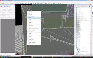
| 99. You are going to notice quite a number of fracture lines from the subtraction operations. We can get rid of almost all of these by right clicking on and edge and choosing "Trim" from the pop-up menu. A good rule of thumb is to start near the top of the shape and trim your way downwards.
| 
 |
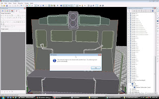
| 100. When you get down to your last few trims, you will encounter this message. Leave the remaining edges for now; we will have to do a special operation on the cab later so that the fracture lines don't mess up the paint.
| 
 |
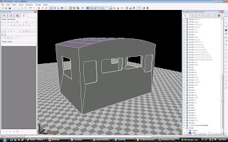
| 101. Next, select all of the interior faces of your window ("3", CTRL, click or drag on each face) and delete them.
| 
 |
| 102. We need to round the cab off. Simply divide the top side of the cab into several sections, then lock your "X" and "Z" axis. Select each edge on the top of the cab ("2", click) and pull it up until the desired shape is formed.
| 
 |
| 103. Run the Double-Side plug in on the cab.
|  |
| 104. Extrude the interior of the cab by selecting all of the interior faces ("3", hold CTRL, click all faces, right-click), and choose "Extrude Region". You also need to check "Extrude using face direction" and set the extrude length to .11 in the Parameters section under the Shape Operations panel. I made the walls of the cab thicker because I like the "heavy metal" look of a locomotive. Everything is built up tough to withstand the millions of miles these units will be traveling.
| 
 |
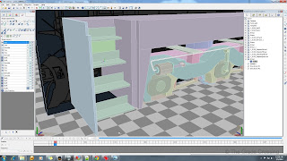
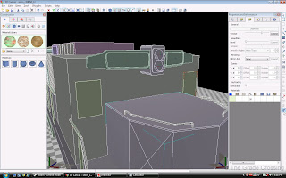
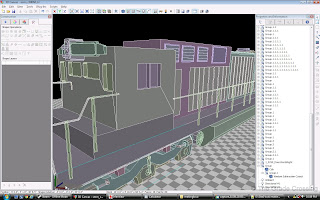
| 105. Right-side doors and vents. Most of them are just simple reshaped cubes that will have details painted on with Diffuse and Normal maps.
|  |
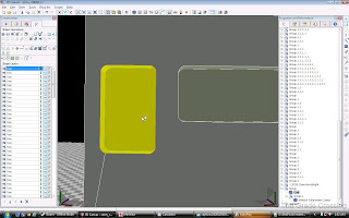
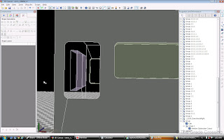
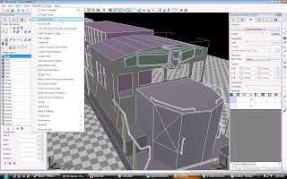
106. To make the panels that have the extruded "X" on them, simply choose the face, ("3", click face), then right click and choose "Split" and X-shaped extrusion. You can control how far the split sticks out in the "Parameters" panel.
| |
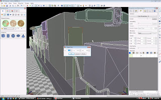
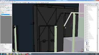
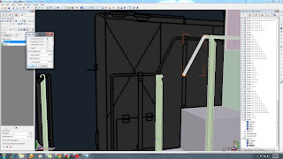
| 107. Handrail stanchions are pretty generic, and there are many ways to make them by pushing, pulling, and deleting faces on a resized cube. After we get our stanchions in place, we resize a cylinder to about and inch in diameter (.11), give it a longitude of "6", and reposition it on the locomotive so that it will fit through the stanchion loops. You can extrude it to length, or simply select the end face and pull it to length. After that, select a face and begin using the Piper plugin to make all the twists and turns necessary.
| 
 |
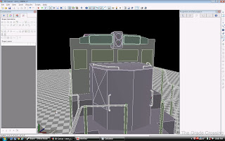
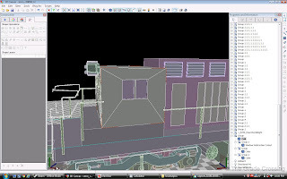
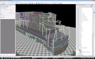
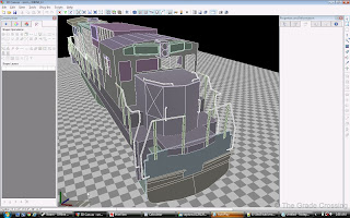
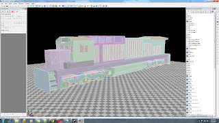
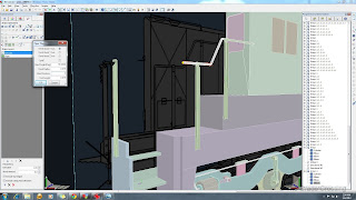
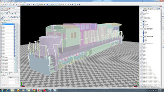
| 108. Our locomotive rough shape is basically done. We stand at about 13,000 right now, so we have about 6900 left to do our detailing.
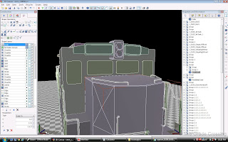
|  |
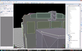
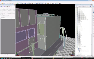
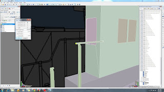
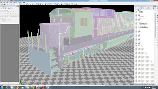
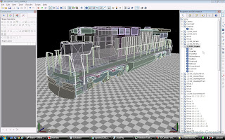
| 109. As you have probably noticed by now, there is a good bit of clutter in the Scene Hierarchy Although we are far from finished, it's probably a good time to start organizing all those parts into groups. All other parts, except for the bogies, will be sub-groups of the Engine group. We will put all of the hood blockings into the root of this group.
|  |


No comments:
Post a Comment