205. The first step to creating a cabview is to open the locomotive shape that we have just constructed and save it as a different file. This file will constitute the cabview. For naming, putting a "_cabview" suffix on the end of the name should be sufficient to differentiate it from our external model.
After you have saved the cabview model, we will begin constructing the interior model by removing everything from our locomotive that will not be seen from inside the cab. The only things you will need to save from our original model is the cab interior, the hoods, decking and whatever handrails can be seen when looking out the window on either side of the cab. Delete any parts or faces that won't be seen. Get rid of as much as you can without sacrificing view quality. We need to save polys here because we will be adding some high detail stuff to the cab interior.
|
|
| 206. We will start our cab detail by hiding the cab itself, then rounding off our captain and mates chairs inside the cab. Do this by running the Chamfer operation on the chairs that we made for our external view.
|
|
| 207. Now lets get down to the nitty-gritty by starting on the control surfaces. It will be of great help here if you have photos of the interior of the locomotive that you want to make. Start by pulling and shaping two cubes to use as the back plates for our Dynamic Brake and Throttle controls.
|
|
| 208. Make the housings for these controls by dragging a cylinder onto the scene and reshaping to size. We want the cylinder to be a bit oblong, so it's given a narrower X-axis.
|
|
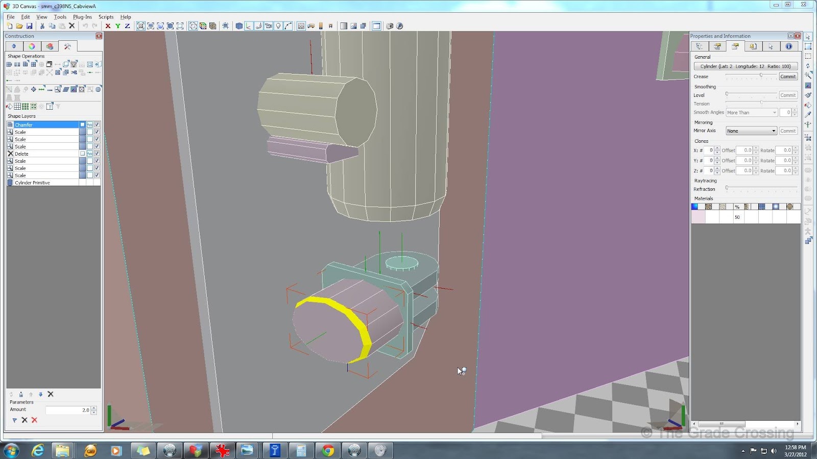
| 209. Run the Chamfer plug on the shape to taper the top of the housing.
|
|
| 210. Choose and delete the points on the back half of the cylinder ("1", Hold CRTL, click on all desired points to select, Delete). Do the same for the bottom side to get a half-cylinder.
|
|
| 211. Divide the back edge into two edges by placing a point in the middle ("2", right-click edge, Divide, 2 Edges).
|
|
| 212. After placing the point on the back edge, you need to connect each point on the front edge of the housing to this new point. Do this one by one by selecting the first point you want to connect ("1", click-point), then holding down CTRL, right clicking the rear point, and selecting "Edge" from the pop-up menu. Do this until you have what is shown in the picture.
|
|
| 213. Pull up a bit on the back point, then set the control housing back against the plate.
|
|
| 214. Repeat the same steps for the Throttle Housing, and for the Reverser (not shown).
|
|
| 215. The Train and Locomotive brakes assemblies are basic cylinders that are shaped to fit, with the Chamfering and Taper operations thrown in. These things vary greatly by locomotive model, so again, it helps to have reference photos or measurements.
|
|
| 216. The instrument panels that hold DPDT switches for various controls starts as a cube that is shaped to size.
|
|
| 217. The edges are then extruded outwards, then extruded forward.
|
|
| 218. A few small cube shapes placed inside the panel complete the object.
|
|
| 219. Different styles round out the control set.
|
|
| 220. Cubes shaped to size and flattened are used to make up the back plates for various instruments.
|
|
| 221. The radio starts out as a simple cube shape.
|
|
| 222. We want to make a separate, paintable panel for frequency and channel information, so we will use the Inset tool. Start by selecting the front fact ("3", click on face), and in the Construction Panel, under Shape Operations, click on the Inset button.
|
|
| 223. Once we have created a face within the main face, we will need to move the edges ("2", select edge, pull) until we have a box the size of our information panel. To make this easier, I have temporarily turned the entire radio straight on. Then, trim off the excess edges ("2", right-click, "Trim").
|
|
| 224. We start making our radio buttons with simple cubes, the duplicate them and reshape until we have all that we desire.
|
|
| 225. The second box is made the same way, but this one has a guard for an emergency control, so we will add that as a Chamfered cube.
|
|
| 226. The base for the Horn pull-lever are simple cylinders shaped to size.
|
|
| 227. Now we will put in the gauges on the instrument panel. We don't want to damage the entire control stand with fracture lines, so we are going to have to take a few extra steps here. First off, divide the top edge of the front of the panel by pressing "2", right clicking on the top edge, selecting "Divide", then select "4 Edges". Do the same for the bottom edge of the panel.
|
|
| 228. Select the top and bottom points, right click, and select "Edge" from the pop-up menu. Do this for all points until you have four different sections on the control panel.
|
|
| 229. Select one of the panels to Duplicate, and make a copy of it high enough so that you can work on it without interference.
|
|
| 230. Once you have run the Duplicate plug, select the new face and run the Double-Side plug-in on it.
|
|
| 231. Go to the backside of the new shape, select the back face, and Extrude it to make a cube. The reason we are doing this is that we will be using Boolean subtraction on this object (remember the cab window cut-outs?) and you cannot subtract from a flat plane.
|
|
| 232. Create a cylinder that is about 1/2" (.05) thick, orient it into the cube we just created, select both the cube and the cylinder, and click on the Shape Subtraction button from the right side Edit Toolbar.
|
|
| 233. Right click on the extra edges and use the "Trim" command to get rid of as many of the edges as you can.
|
|
| 234. Delete the back, top, bottom, and sides of the cube, leaving only the gauge face.
|
|
| 235. Delete the face on the original instrument panel from which you made the face copy, and place your new gauge in that slot.
|
|
| 236. Duplicate the effort three more times to fill out the panel, and place needle pegs in the center of each gauge.
|
|
| 237. The On and Off buttons are simple cylinders, one placed inside the other.
|
|


No comments:
Post a Comment