| 1. Start with a cylinder primitive with 12 longitude panels.
|
|
| 2. Resize (Right-Click, "Scale", "To Size") the cylinder to the figures shown. This will give a 5" diameter mast that is 15' tall. I have no official measurements from this type of mast, but I do have rough figures gleaned from the Invensys SafeTran site.
|
|
| 3. Move your camera view around to the bottom of the mast, select the bottom face (3+Click), go to the "Plug-ins" menu at the top of the window, and select "Shift Centre on Selection". This will move the center of the object to the middle of the bottom of the mast. This will make it easier to place the asset on the ground.
|
|
| 4. Now move back above the grid, and in the Properties and Information Panel, zero-out all of the values so that the object is in the exact center of the grid and sitting precisely on top of it.
|
|
| 5. If the signal head is in the way of your work on the post, select all of it's parts in the P and I Panel, right click, and select "Hide". This will move it out of the way until we need it later. In the mean time, we need to go ahead and name the group "Post" and the object name as well. This group is where all of the other objects for the post will reside.
|
|
| 6. We are going to be a little more detailed with the Post object for the signal than we were the Head. We need an end cap, so select another cylinder primitive and place it at the top of the post. Resize it to x.45, y.18, z.45. This will give us the bottom of the end cap that is 5.5 inches in diameter and 2 inches tall. After you have resized the cap, use the P and I panel to move it into position over the post. Lock the X and Z axis button (Primary Tool Bar) and drag the cap straight down until it touches the post.
|
|
| 7. Now drag a sphere primitive from the Construction Panel onto the cap that we just made and placed. You need to give this sphere a Longitude of 12 so that it matches the post.
Once placed, select and delete all of the bottom half of faces of the sphere. We only need the top of it.
|
|
| 8. Resize the half-sphere so that it matches the diameter of the top cap we made and flattens it out. This is the top part of the top cap.
|
|
| 9. I flattened it out a bit more before final placement.
|
|
| 10. Now, you need to unhide the signal head and place the center of the head exactly on top of the mast, and then move the head forward 1 foot.
|
|
| 11. Once you have the head in it's final position, pull a cylinder primitive and "attach" it to the mast. Select the shape in the Properties and Information panel and rotate it 90 degrees on the X axis. Then, position it at 0.0 on the X axis, and position the far end of the cylinder buried into the main post until you can't see any bottom edges. This will simulate a welded arm for attachment of the signal head.
|
|
| 12. We need to bend an elbow that will go up and provide the attachment point for the head. Select the end face (3+Click), then in the Plug-Ins menu at the top of the window, select from the drop down menu "Shape-Builder", "Piper". Plug in the values shown. The Piper tool takes some time to get used to, but once you do, you can bend just about any shape that you might need in the game.
|
|
| 13. Now we have a nice bendy to run up to the head. Select the top face of the elbow (3+Click), and then Right-Click "Extrude". Plug in the values from the Shape Operations tab of the Construction Panel.
|
|
| 14. Remember the end cap that we needed for the main post? Well we need another one (don't want rain water getting down in the post, so we?).
|
|
| 15. Well, I kind of goofed here. The signal arm isn't long enough to reach the signal. No worries though, we will simply lock the X and Y axis and pull the arm forward until the swivel attachment sits directly in the middle of the end cap. Then, we will go to the rear of the arm, select the rear face (3+Click), right click on it, and choose "Extrude".
|
|
| 16. Extrude the arm until the bottom edges no longer show on the outside of the main post.
|
|
| 17. Remember what I said earlier about signals being mostly made of cylinders, and cylinders are made of lots of polygons? Well signal posts are the worst! At some point it would be a good idea to go back through your object, by hiding individual parts, and deleting faces that will not be seen. The end of the signal arm is a good example because it its buried in the main post.
|
|
| 18. You can be as simple with these things or as detailed as you want to be, just keep in mind more polygons (2 per face) mean slower game performance. Here, i'm adding a splice plate to the arm. It's a simple cube that's been placed, reshaped, and centered in the arm.
|
|
| 19. I've even decided to add a few nuts to simulate the bolts holding the signal arm to the welded extension from the mast. Rivets and nuts are selectable from the Plug-Ins, "Shape Builder" menu. You select the face of the object you want nuts on, dial in your sizes and your inset, and the Builder will put a nut in each corner.
|
|
| 20. Go back up to your top cap and duplicate the cylinder section. This option is available in the Edit Toolbar, right-side, bottom button. Right click to set your position and such, hit OK, then click on your object to be duplicated and left-click on the duplicate button to copy it.
|
|
| 21. I resized the shape to be 1" in height. This piece and the next one shown will simulate the post clamp that will attach the ladder.
|
|
22. Make the ladder. These are spindly little things; according to the plans, they are only 8 inches wide, and the rungs are placed 15 inches apart. This particular model does not come with a safety cage or platforms. This seems peculiar to me, since the railroads highly emphasize worker safety, but it's in the plans so this is the way we will do it.
Place a box primitive on the ground and resize it as shown. This will give us our narrow ladder, plus a bit to sink into the ground for "extra support". |
|
| 23. The ladder bends at the top to tie onto the signal post, so we will use the Piper Plugin again to simulate the bend. We are going to bend the curve at 85 degrees instead of 90 because the ladder tilts at 5 degrees angle to the post.
|
|
| 24. Using the Properties and Information panel, tilt the ladder 5 degrees towards the signal post. You will then need to position the ladder a close distance from the post, with the bent the same height as the post clamp.
|
|
| 25. Select the face of the bend, right-click, and "Extrude" the face. In this case, just a little over 6 inches will be sufficient to "connect" the ladder to the clamp.
|
|
| 26. We've got more faces than we need. Select the outside faces of the ladder, front and back, (3+Click) and delete them.
|
|
| 27. Now select the upper part of the ladder, go to the "Plug-Ins" menu, and select "Double-Side". This will produce the side rails for the ladder. Do the same with the lower part of the ladder.
|
|
| 28. Bring in another cube primitive and resize it as shown. This is going to be the ladder rung. You don't need the whole cube, so select the front face (3+Click), go to the "Duplicate" button in the Edit Tool Bar to the right and right-click, zero out all the values except the Duplicates field, hit OK, then left-click on the duplicate button. Delete the original cube and you should see your single sided ladder rung hanging in the air. Click on it, go to the Plug-Ins menu, and select "Double Side".
|
|
| 29. Move the run into it's first position.
|
|
| 30. Click on the rung, then go again to the Edit Toolbar and right-click on the "Duplicates" button. Set the value for 10 duplicates, shift their Y-axis to -1.25. This will give 10 rungs at fifteen inches apart, just like the prototype. Click OK to close the Options menu. Left-click again on your rung, then left click on the "Duplicates" button again. You should see ten more rungs appear in the air behind the ladder.
|
|
| 31. Now of course they are not in the proper position on the ladder, so we will need to lock the X and Y axis buttons on the Primary Toolbar and then drag each rung until they are between the ladder rails.
|
|
| 32. We need a couple of stays for this flimsy little thing, so we are going to duplicate the clamp assembly and the tops stays and modify them to suit our needs. Select the inside and outsides of the top stays.
|
|
| 33. As shown, we are going to duplicate them -8 feet below where they are now. We are also going to duplicate the clamps and nuts.
|
|
| 34. After duplicating these parts, we will need to elongate the stays to reach out and weld to the ladder. Select the front-edge of the nearest stay (2+Click), then right-click and choose "Extrude" from the pop-up menu. We need the stay to just touch the ladder without leaving a gap. Do the same for the other stay.
|
|
| 35. A look at out completed ladder and the naming in the Properties and Information panel. Everything has a unique name, and the groups have been assigned LOD numbers. You can have duplicate names and use the "Unique Names" plug-in to sort them out, but I prefer to name things as I go along to avoid confusion.
|
|
| 36. Another object for the post that takes artistic license, just as the signal backs do. This is the base of the post. There really is no need to build a base that extends much below ground, a round or square base about a foot high, painted in concrete will do. But, I put a prototypical base on my signals just in case I want to have a few lying around in a junk pile or near some MOW equipment. The base plate and nuts were made the same way as the joiner plate.
|
|
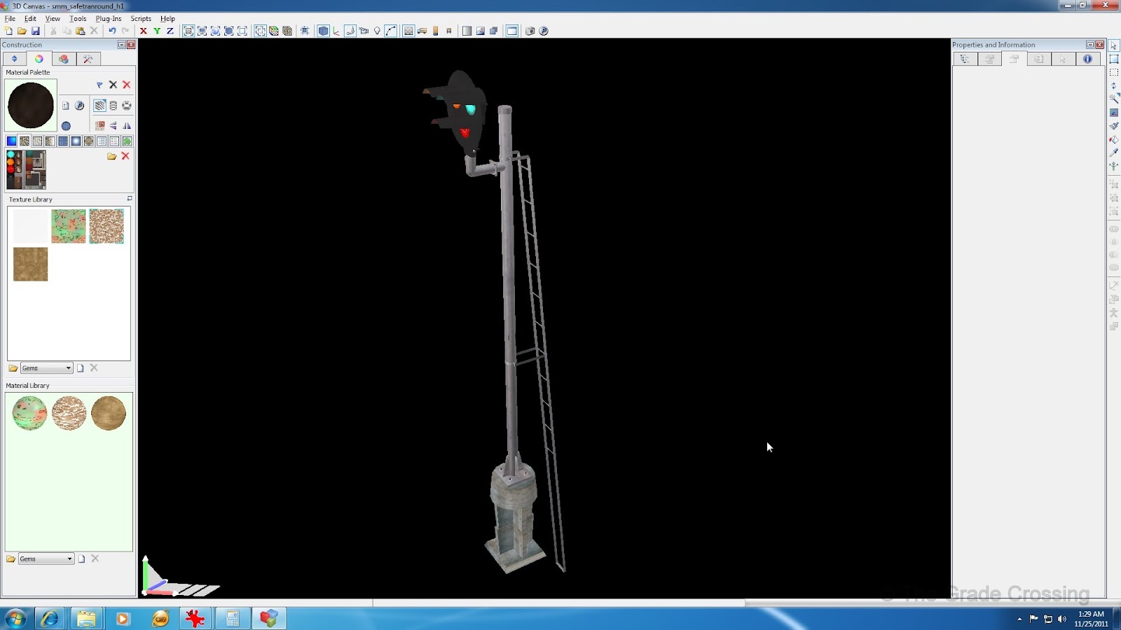
| 36. A little paint on the post and ladders, and the next step we will take will be getting this thing in the game!
|
|
| Before finishing though, go back to the Material Manager ("Plug-ins", "Information", "Material Manager") as we did with the signal head and make sure all parts under the Post group have the shader "TrainBasicObjectDiffuse.fx" attached to them. If not, then check all of the parts under the Post group. Click on one of the blue boxes in the post group, then type in the name of the shader under the "Field Value" box to the right. Check the "Field Value" box, then click "Apply". This will apply the shader to all checked parts.
|
|


No comments:
Post a Comment