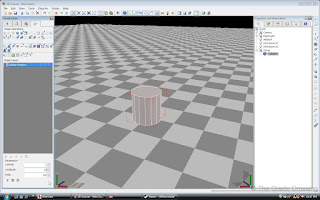
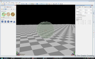
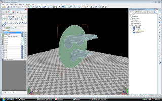
| 1. After opening the 3DCanvas program, move to the center of the grid. Right click anywhere on the grid and select "View / Solid Outline"
| 
|
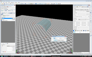
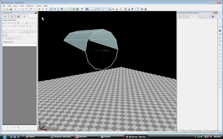
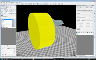
| 2. From the Primitives bar in the Construction Panel on the left, select a cylinder and drag it to the center of the grid. We need to try to keep the polys in this asset down so as not to slow down the game, so select the "Shape Operations" tab in the same panel, and in the "Longitude" field, type 12.
| 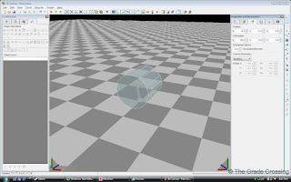 |
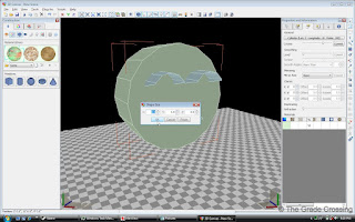
| 3. Select the cylinder by clicking on it. Then, using the position fields (third tab, Properties and Information panel menu, right side), turn the cylinder primitive 90 degrees on the x-axis (side-to-side) so the ends will be facing down the z-axis (front-to-back).
|  |
| 4. Using the position fields (third tab, Properties and Information panel menu, right side) position the y-axis (up-down) so the object is floating 15' in the air above the grid.
|  |
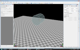
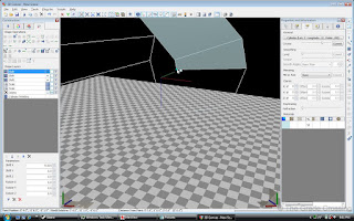
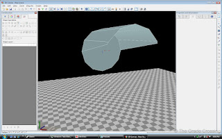
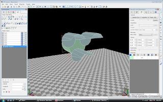
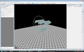
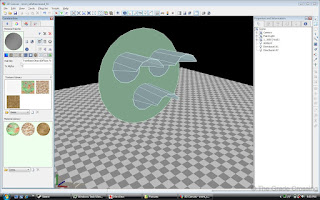
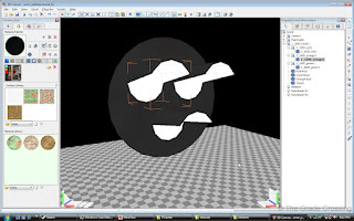
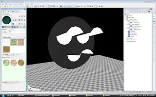
| 5. Select the front face and the bottom faces of the cylinder. Do this by holding down the "3" key, then clicking the front face. Then, hold down the "CTRL" key and click on the rest of the faces to be selected. Once you have selected the desired faces, hit the "Del" key. You should end up with this:
|  |
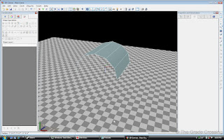
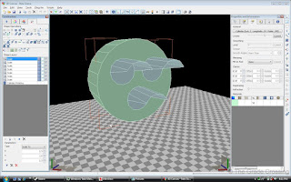
| 6. Resize the partial cylinder (Right Click the object, "Scale", "To Size") to x-.75 and z-.75, leaving the y-axis as is. This will approximate our signal lights to a prototypical nine inches in diameter.
|  |
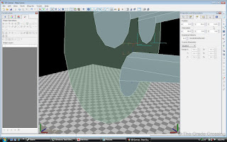
| 7. Lock the z-axis by pressing the "Z" button in the top left corner of the Primary Tool Bar. This will keep the model and anything you might select from moving in a forward-back motion. Now, select the point on the lens hood by pressing "1" and clicking on the point that turns blue. It will turn yellow when you have it selected. Move the point along the z and y axis until you have it positioned on the model as desired.
|  |
| 8. Do the same to the other side of the signal lens hood.
|  |
9. Now, select the object by clicking on it. Click on "Plugins" at the top of the screen, and from the drop-down menu, select "Double Side". This will give faces to all sides of the lens hood.
Rotate your view around to the other side of the model. Select the old "bottom" face of the model (by pressing "3" and clicking). Go to the "Plugins" selection again, and select "Shift Center on Selection". This will make this face the center of the model, at coordinates x-0, y-15, z-0.
|  |
| 10. Signal assets are basically made of a lot of cylinders. In turn, cylinders contain a large number of polygons, which can slow down game performance. As such, we want to save polygons wherever we can by getting rid of those that will not be seen in the game. The end of this lens hood will be up against the glare hood, so we won't see it. Select the face (3+Click), and delete it (Del).
|  |
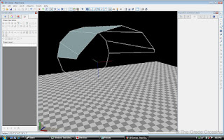
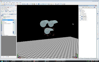
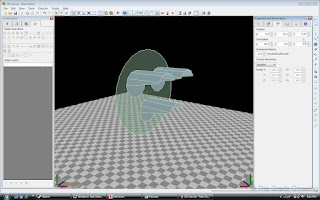
| 11. Run your camera around to the front side again and view the completed signal hood.
| 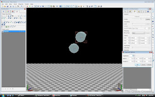 |
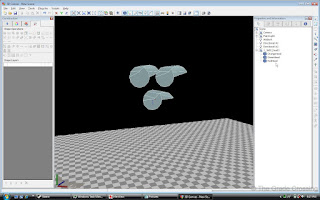
12. We can duplicate the lens hood to make the other two signal lights. RIGHT click on the Duplicate button (Edit Tool Bar, Last Button). This will bring up a menu in which you can plug values as to where you want your duplicate object to go. Plug in the values shown. If this were a vertical inline signal, you would simply put +1 or -1 in the y-axis field. If this were a searchlight, you would leave all values at zero. Click OK.
Now when you left-click the duplicate button, the new object will appear.
| 
 |
| 13. We need to tidy up a bit before moving on. Name each lens hood so we can identify what type of lens will go in it - red, orange, or green. Once we have named each lens hood, we will group them together in the folder named 1_1600_red1. The "1_1600_" is the LOD number and tells the game that these particular parts will render up to a mile. The "head1" tells the signal script which head (if there are multiples) to render the signal light on.
| 
 |
| 14. Now we need to make the glare hood. Select a cylinder primitive from the Construction panel, and using the above steps, turn it 90 degrees as we have done before.
|  |
| 15. Resize the cylinder using the x,y,z coordinate that come up when you right-click and see "Scale" "To Size".
|  |
| 16. After the resize, use the coordinate input in the Properties and Information pullout to the left (third tab), to move the y-axis coordinates up to the signal lens hoods.
|  |
| 17. Once there we make a fine adjustment to the size (Right-Click the object, "Scale", "To Size").
|  |
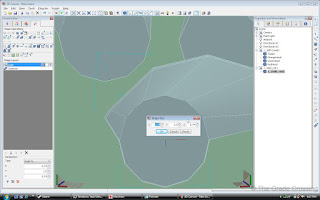
| 18. Sixteen sides is a little rough for a round signal glare hood, so we need to adjust how many sides the cylinder has. In the Construction panel to the right, click on the Shape Operations (fourth tab) to bring up the panel. Now click on the glare hood to show every operation that has been done so far. Go to the first operation named "Cylinder Primitive" and change the Longitude to 24.
|  |
| 19. Now we have a much smoother shape for the hood.
|  |
| 20. Get rid of the extra parts by selecting every face (3+Click) that we don't need and deleting them. The only face you should leave will be the front side.
| 
 |
| 21. Now from the front side, select the glare hood object, select "Plugins" from the top menu, and click on "Shift Center to Selection". Afterwards, in the position input again, the x-axis should be 0, the y axis should be 15.5 (you may have to drag the hood up or down to get it into the correct position), and the z-axis should be .10. This will set the glare hood a little behind the lens hoods so as not to interfere with the lens shine.
|
 |
| 22. Double-side the glare hood, name it, and place it into the group with the other hoods.
|  |
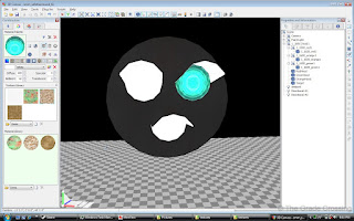
| 23. Pick the inside faces of one of the lens hoods, using the 3+Click. Make sure to select all of the faces. When you have selected them, right-click on the "Duplicate" button and make sure all of the inputs (except for the quantity) are zeroed out. We are going to create the actual signal lights by duplicating the selected faces in the exact position of the selections. When you are sure of your selection and position, press the Duplicate button.
|  |
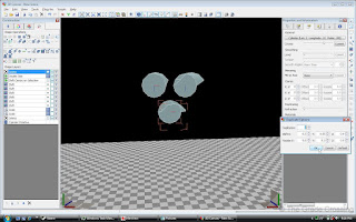
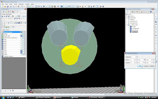
24. To the right in the "Properties and Information" box, you will see a new shape appear. Select this shape and name it as shown in the photo. This is your red lens. "1_1600_" is the LOD number, the distance that the signal will render up to. The "red1" will be called by the signalling script to render when a red signal is required in the game.
After renaming the part, resize it and make it slightly smaller than the original lens hood.
CORRECTION: The Shape Size numbers on the screen should read "x=.74, y=.90, z=.74".
|  |
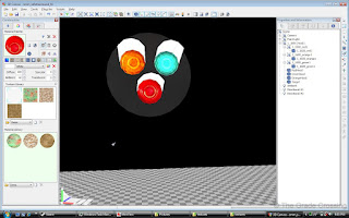
| 25. Repeat the same procedure with the green (top right) and orange (top left) signal lens hoods. Name the parts as shown in the photo. You don't necessarily have to have the LOD numbers, but the parts must be named red1, orange1, and green1, a well as their respective group names.
| 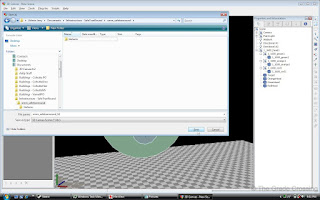 |
| 26. Right now would be a good time to save our work. I have already set up a folder that will contain the 3DC file as well as the textures and IGS files later. Name the file something that will help you differentiate the head file from the rest of the objects later. By the time you are finished making a complete signal set, you may have 20 or more assets, so it's good to organize early to avoid confusion later.
|  |
| 27. There are many types of casings that protrude from the back of the signal hoods. We are not going into detail about this, as the things take a good bit of time, trial and error, and artistry to make. The best thing to do is try to get schematics and measurements of these before trying to make them.
| 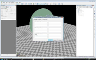 |
| 28. Basically, we are done for now with shape making. We are now turning our attention to object decoration. First thing we need to do is right click on the black part of the screen and select "Scene Properties" from the pop-up menu. Go to the "Custom Fields Tab". Under the first Material Custom Field input row, type in "Rail Sim". We will not be using alpha in this model, but you can put it in there anyway just in case.
|  |
| 29. In the Construction Panel, under the second tab (Material Pallet), enter the values shown into the Diffuse and Ambient fields. The TSX engine in RW3 brightened the game to the point of a nuclear bomb flash, so we have to use a low diffuse property to keep the model from being to bright. Ambient setting at 2 will keep the model from glowing in the dark. Leave the Specular and Translucent fields blank.
|  |
| 31. In the eighth tab under the Material Pallet you will find the fields that we just entered in the Scene Properties box. This is where you put your shaders. We are not using Bump, Specular, or Environment maps on this model, so we will put in TrainBasicObjectDiffuse.fx. This is the equivalent of TexDiff. We will use this shader on all non-brightening parts of the model.
| 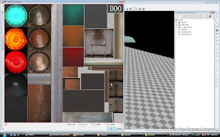 |
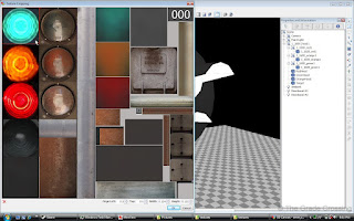
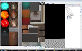
32. The second tab in the Material Pallet is the Diffuse Texture Slot. You will see a folder. Press it and find your diffuse texture (assuming you have already made it). After loading it, press the button just below the checkered box to open the texture for selection.
I'm selecting the dark box in the lower left corner of the texture. This is a generic black non-snow texture for use on the hoods and body of the signal head.
|  |
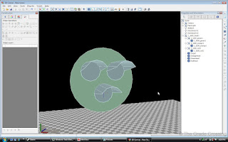
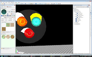
| 33. I have flood filled the glare hood and the lens hoods with this texture. The actual lens shapes will still show untextured.
|  |
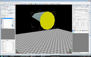
| 34. Now I'm picking a texture for my green lens.
|  |
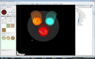
35. After I have picked my texture, I go back over to the Material Pallet, pick the Attributes tab again, and put "Tex" in the Rail Sim properties slot. Tex is a full-bright legacy shader which turns the part that is painted with it on, day or night. We are going to brighten the part up even more by turning the Diffuse value up to 100, and the Ambient value up to 40. At this point, you may want to hide the outer lens hoods (Right Click part, select "Hide" from the pop-up menu) so you don't mistakenly paint them with the on-lens color.
A word of caution about Ambient settings - In Railworks 2, turning up the Ambient value of the asset would make it glow in the dark. This was especially useful if you wanted to do night time windows with various gradients of brightness. However, Railworks 3 has changed the value of Ambience, and any number over 30 or so will produce a soft-fuzzy glow. This is good for neon lights, and maybe a bit for this application, but you don't want to over-do it.
| 
 |
| 36. Repeat this procedure with the orange and red lenses.
|  |
| 37. We also want to give a realistic "glow" effect to the inside of the signal hoods. Using the Tex Shader and the same settings that we used to paint the "on" lenses, I go back to the pre-made diffuse texture and select a soft glow for the inside of each lens hood.
|  |
| 38. Now we go back, select all of the faces of the inside of the lens hood-on shape and paint it with the soft glow of it's respective color.
| 
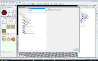 |
| 39. That basically finishes the signal head. We need to check our work to make sure we have our naming conventions right and the correct shaders applied. Go to "Plug-Ins" at the top of the screen, select "Material" near the bottom of the drop-down menu, then select "Material Manager". This information box will allow you to batch-apply shaders, Diffuse, Ambient, Specular, and Transparency settings. Doing this through the Properties and Information panel can be tricky, so I prefer to use this Manager instead.
| |


No comments:
Post a Comment