| 365. The starting point to getting our locomotive in the game involves creating Provider and Product folder within the Railworks source folders. I am going to set this up in the same way that RSC does for it's DLC locomotives. Open up Railworks, and under the Tools and Doc tab, click on the "Source Folder" button.
|
|
| 371. Once inside the Source, you need to create your Provider folder. Here it will be "SMMDigital".
|
|
| 372. Within the SMMDigital provider folder, I create a product folder for my locomotive called "C398".
|
|
| 373. Within the C398 product folder, I create three sub-folders - Audio, Particles, and RailVehicles.
|
|
| 374. For right now, we are only going to concern ourselves with the "RailVehicles" folder. Within that folder, create two more sub-folders - "Couplings" and "Diesel"
|
|
| 375. Let's branch off for a moment into the "Couplings" directory. Within that directory, set up a folder called "Buckeye". Within Buckeye, create a folder called "Type-E". And within that folder, create a directory called "textures". I don't know why RSC set things up this way, I'm just following them for the greatest chance of success in getting this locomotive to work the first time around.
|
|
| 376. Now back up until you get to the Diesel directory. Inside of it, create a folder for whatever your locomotive is, in this case a C398.
|
|
| 377. In the new locomotive folder, create a folder for the roadname that you are producing. If there are several roadnames, then create one folder for each one.
|
|
| 378. Inside of the roadname folder, create two more directories - "Cabview" and "Engine". Inside both of these folders, create a sub-folder called "textures" (not shown).
|
|
| 379. Now, back up into the folder that contains your individual road names and create a directory called "Default". This folder is where files that are used in common across all of your locomotives will be placed.
|
|
| 380. Create five directories within the Default folder - "Bogies", "CabView", "Driver", "Engine", "Simulation". Within the CabView, Driver, and Engine folders, you will need to create a "textures" folder.
|
|
| 381. Now that our directory structure is created within the Source folder, we need to start transferring files from our work folder to the Source. We will start by moving our coupler IGS and it's associated textures to the Couplings\Buckeye\Type-E folder.
|
|
| 382. We are going to place our Cabview model and it's associated .ACE files into the "Diesel\C398\NS\Cabview" folder.
|
|
| 383. And finally, place our exterior model files in the "Diesel\C398\NS\Engine" folder. It is not shown here, but your animations that belong inside your cab should be placed in the "Default\Cabview" folder, and the animations for your locomotive exterior model should be placed in the "Default\Engine" folder.
|
|
| 384. Before we start working with the Locomotive Blueprints, there are a few satellite blueprints that we need to deal with first. Open up the Railworks Asset Editor and navigate to your Provider folder, then to the Product folder that contains your coupler. Right-click on the "Type-E" folder and choose "New Blueprint". Then from the pull-down list, choose "Coupling Type" blueprint.
|
|
| 385. In the first line of the Blueprint, right-click on the name of your coupler IGS file and select "Copy Filename". Then, paste it in the field beside "Uncoupled Geometry".
|
|
| 386. If you know anything about the physics of couplers, then you could play around with your numbers, but I'm pretty much entering Railworks default values here in the Strength field.
|
|
| 387. All of the values under these fields came from the RSC Dash 9. Since the Dash 9 is the "grandfather" of the C398, there should be some similarities Note that we only have a single coupler geometry file, so I used it in both the "coupled" and "uncoupled" fields. After finishing the field inputs, save the file and rename it to reflect the coupler that it is serving.
|
|
388. The next satellite blueprints we need to make are the Bogie blueprints. Now this is where everything is going to get all arithmeticky on us. Open up your external model in 3DCrafter. Go to the group that contains Bogie 1 and click on it, then click on the Properties and Information tab. The first bit of information that we need is the Bogie Pivot. That will be the value in the "Z-Position" field. We are going to have a lot of numbers to crunch, so I like to make an Excel file so that I can keep up with the measurements for later reference.
|
|
NOTE: Because this is a British program, they don't use a real numbering system ( :P), so you will have to convert your measurements to Metric. You can do this in Excel by setting up a cell that references your Imperial input and divides it by 3.33, as I've done in the examples. Or, you can simply use a calculator to do the same thing. Either way, the metric numbers are what we will be plugging into the program.
| |
| 389. Next, you are going to need the Z-Position coordinates for each of the wheels. Click on the group for each wheel and note the coordinate within the truck in the Z-Position. It is important that you are precise with these measurements. A miscalculation or wrongly entered value could cause your locomotive to SBHH. Record your results.
|
|
| 390. Do the same for your rear bogies.
|
|
| 391. Now, we need some other measurements. First, the length of the locomotive, from the tip of the furthermost part, which would be the kickstep, to the rear of the back kickstep. In this case, it's 68'. The locomotive is actually longer than this, but we don't want to include the couplers. (Nit-Vultures, yes the locomotive is about two feet short. Nothing is perfect, even in your world!)
|
|
| 392. Next is our collision box length. We want this to include the trucks, but exclude the couplers. Here, it's easiest to use the total length of the hoods above the top-plate to calculate the collision length. It would be 64'.
|
|
| 393. Using a cube, you need to calculate the distance from the railhead (scene floor) to bottom of the deck plate. For this locomotive it is 4.17.
|
|
| 394. Then, we extend the cube to the top of the tallest part of the locomotive, in this case the smokestack, to get our overall height (15.69') and our height from bottom of the deck to the top of the stack (11.52'). All of these numbers will be put into the locomotive blueprints later.
|
|
| 395. Go back into the Asset Editor and navigate to your Default engine folder that contains the directory named "Bogie". Right click on the Bogie folder, select "Bogey Blueprint", and rename the result to "YourLocomotive Bogie 01"
|
|
| 396. The first field that we come to in our bogie blueprint is the Wheel Radius. The radius is half the diameter of the wheel, which would be about 21", or 1.75 feet (my measurement includes the flange). Divide that by a Meter, or 3.33, to get .526. This is the number we will plug into the Wheel Radius field.
|
|
| 397. The second field is the axle gauge, which is 4'8-1/2". Translated to Metric, this is about 1.435. The third field references the Group name of the bogie in the IGS file, which is Bo01 (actually it is 1_500_Bo01, but we don't need the LOD number here).
|
|
| 398. Now here is where the measurements that we took in earlier come into play. You will need to insert three axles (two if it's a B-B locomotive) into the blueprint. Each axle will get it's name from the corresponding Group name in the 3DC/IGS file. And each corresponding group name will get it's offset (in Meters) plugged into the Horizontal Offset field. What this does is tell the game engine exactly where each locomotive axle is located for animation purposes. The first axle is located 2.05 meters in front of the bogie pivot, the second axle is located directly under the bogie pivot, and the third axle is located 2.05 meters behind the bogie pivot.
|
|
399. We don't worry about Pivot Offset on this one, so we save the Bogie 1 blueprint and create another one for the rear bogie, Bogie 2. Now if we have done this right, our locomotive will roll along in the game. If we haven't, we will know it real quick like!
CORRECTION - The photo shows the same bogie name in each of the three fields, when it should actually be "bo02wh01", "bo02wh02" and "bo02wh03".
|
|
| 400. Now it's time to get bogged down into some serious data entry. In the Asset Editor, navigate back to your Engine Default folder, go to the "Simulation" folder, and right click on it. Create a new Engine Simulation blueprint and name it "Your Locomotive Simulation". Once you have done that, fill out the name fields shown and give it the "Locomotives" category (yes, RSC spelled it wrong!).
|
|
401. This blueprint is where all of the physics data about your locomotive is entered. If you have detailed information and technical specifications about how your locomotive operates, now is the time to whip it out. If you don't, until you get that information, you will have to use data from a similar locomotive in Railworks. To view this data, get a copy of RW_Tools and check out the Simulation Blueprints of the other locomotives in the game. That info is usually located in the locomotive's "Default\Simulation" folder.
Because I'm not going to Brazil to get the data for a C39-8, I'm going to create a sort of hybrid by using what data I do have and data from the Dash 9. The Dash 9 is the "grandchild" of the C39. First, I'll start out by filling in the first Engine Sim Component. Start by creating a "Diesel Electric Subsystem Blueprint"
|
|
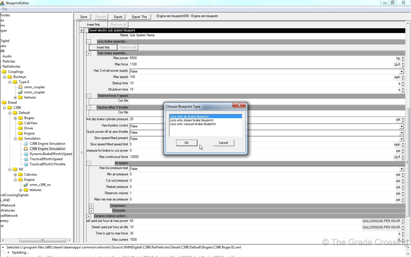
| 402. Expand the box next to the "Loco Brake Assembly" and then click on "Insert First". From Choose Blueprint Type, click on "Loco only air brake blueprint". Expand the box next that header and click on "Insert First". You will then be presented with fields under the header "Loco only air brake data blueprint".
|
|
| 403. Whatever data you have for these fields, enter it here. Remember, if at all possible, get the detailed specs for your particular locomotive. Loading the specs from an SD40-2 or a Dash 9 will make your locomotive run, but it won't run realistically for your particular model.
|
|
| 404. Moving on to the Train Brake Assembly, expand the box next to the "Train Brake Assembly" and then click on "Insert First". From Choose Blueprint Type, click on "Train air brake blueprint". Expand the box next that header and click on "Insert First". You will then be presented with fields under the header "Train air brake data blueprint". Fill in all the data fields available.
|
|
| 405. The next section involves information such as horsepower, braking, fuel consumption, and such. Provide whatever info you have for your locomotive in the fields. After you are finished filling out this blueprint, save it.
|
|
WARNING: The next section is part technical, part bullshit, and part guesswork, so you may want to skip to point 406.
In the engine simulation blueprints, you will notice references to three .dcsv files. These are "comma separated value files" that contain tractive effort information for a particular locomotive. Almost every locomotive in Railworks has them, but the truth is, I have very little idea what all the curves mean. I do, however, have just enough information about them to be dangerous.
| |
| What these three files, "TractiveEffortVsSpeed.dcsv", "TractiveEffortVsThrottle.dcsv", and "DynamicEffortVsSpeed.dscv" does is important to how the locomotive behaves when you are driving it. A good bit of research is required to understand this, and I'm only going to give some basics about a couple of these files.
|
|
The first one concerns how much power a locomotive is able to put to the rails without spinning it's drivers at a certain speed. If you look at the Dash 9 TEvsS file, you will see that the maximum number, 880.799, is achieved when the locomotive is sitting still up to 8.5 miles per hour. Now that number, 880.799, is actually a Newton measurement. If you want to figure out how much that is in pounds-of-force, then simply look up one of the many converters available on the Internet and plug that number in as a Newton. The answer will come up with the Maximum Tractive Effort for the Dash 9, which is over 198,000lbs. If I take the maximum tractive effort for a C39-8 (108,600lbs.) and plug it into the converter in reverse, I would get 483.076 Newtons. Now I know that 0 to 10.8 mph is the C39-8's greatest traction, so if I want to make a tractive effort curve for this locomotive, these are the first two numbers I would plug in. You can start your .dcsv file by opening an Excel file, or any other file that will save as a .csv file, and inputting the speed of the locomotive, followed by a comma and the Newton measurement for that speed.
| |
| Someone at RSC mentioned that you can find Tractive Effort curve charts for most locomotives on the Internet. There is no information of that sort for this locomotive, so I had to pretty much create a crude TEvsS curve chart for this locomotive. I say crude because it's more of a straight line than a curve. I don't know the specifics for each speed number on the Dash 9, but I do know that at the top speed on the chart, the D9 loses 88% of it's tractive effort. I would figure this is because as the speed of the train increases, it takes less power to keep it moving because it's huge mass is helping to push it along. Anyway, I took that percentage and figured the possible bottom tractive effort number for the C39-8, divided it by the number of speed ranges (speed is the left column, TE is the right column) in the TEvsS chart, and plugged that number in. I have no idea if it's right, but it's better than nothing.
|
|
| The TractiveEffortVsThrottle.dscv seems to be a bit more straight forward. It divides the throttle up into percentages, from 0 to 100, and the TE Newton number is divided by the number of percentages "notches" (11) and plugged into each one. I have seen in at least one post at UKTS that these numbers are useless and don't really affect how the loco moves like the TEvSpeed information does.
|
|
As far as what the "DynamicBrakeVsTractiveEffort.dcsv" numbers mean, it will take more research to figure that out. For now, I simply copied the values from the D9 to my own file of the same name.
|
|
| 406. And now for the moment we've all be waiting for! Go to your railroad's Engine folder and right-click on the IGS file for your particular locomotive. Choose "Engine Blueprint" from the pop-up fields.
|
|
| 407. Give your locomotive a unique name that will show up in the Scenario Editor.
|
|
408. The first field we come to is the Rail Vehicle Component numbering list. If you are using dynamic numbering, then this is where you enter the list of numbers that will be used. A simple list of numbers plotted in Excel and saved as a CSV file will work. This locomotive will have any of 114 different road numbers to choose from. For this to work correctly, make sure that you have two columns of zeros, followed by the numbers you want to use.
|
|
| 409. The next two fields will involve your couplers. Put in the information for the couplers that we blueprinted earlier here. Don't worry just yet about all the coupler pivot points.
|
|
| 410. Starting with the Mass input field, this is where we put in data about the size of our locomotive from the measurements we took earlier. The front and rear pivots are the length of the locomotive divided by two and converted to metric. The collision length is the length of a box that extends just inside the step wells.
|
|


No comments:
Post a Comment