If you have ever seen the movie "The Empire Strikes Back", there is battle where the forces of the Rebel Alliance are fighting against lumbering Imperial war machines called All Terrain Armored Transports. They looked like giant metal elephants. Back in 1980 when ESB was made, there were no computers to animate these hulking machines. They were physical models that were moved piece by piece, frame by frame, by special effects artists between shots. It was a painstaking and time consuming process, but the effort won the movie kudos from sci-fi fans and the movie industry in general.
|
|
This process, called "Stop-Motion Animation", is very much akin to what we will be doing as we animate the controls for our locomotives in Railworks. It is a bit more streamlined since we are using computers, but will still be much like those Imperial Walkers from so long ago.
| |
| By this point, you should be completely finished with you exterior and cab view models, with no more moving parts to be added to them. What I do with mine now is save them as "Master Animation" models that will be used, unchanging, over and over again to produce the animations for the final locomotive. If you do change this model, then you will have to re-export it as an IGS file to Railworks in order for the changes to appear. For example, if you decide to add a new lever and animation for that lever, you will install the lever in the Master Animation model, then export it to Railworks. Then, you will animate that lever and export the animation as an IA file to Railworks.
|
|
| 337. Open up your animation master model. You could do all of your animations in one model, then export each animation individually but I prefer to save a new file with each animation I do as it gives me a few backups in case I screw up. Once you are in, go to the Main Menu, click "View", then click "Show Animation Toolbar".
|
|
| 338. The Animation Toolbar at the bottom of the window is where we will be working with each frame of our part movements to create animations. Click on the picture for an explanation of it's controls.
|
|
| 339. The first thing you will want to do is reduce the number of keyframes that you will use to animate your part from the 100 that are default to just one more than what you will need to animate the part. The maximum is 16 keyframes, but for this part, we will only need ten, or about one second, of animation. You can do this by clicking the second button from the left on the top of the Animation Toolbar.
|
|
340. I'll start the animation process with the Engine Run circuit breaker. Click on the button on the far left of the Animation toolbar to Animate the scene. Click on the part that you want to animate. It will show up in the Animation Timeline, along with a red dot in the first key frame. This will denote the opening position of the part to be animated.
NOTE: Ignore the white plane that runs up and down through the circuit breaker. I used it merely as an animation guide for the part, and it will not show up in the actual locomotive.
|
|
| 341. Next, click on keyframe for the next part position in the animation.
|
|
| 342. Move the part to it's desired position. Once it has been moved, a blue dot should appear in that keyframe. If it does not show up, then click on the blue Keyframe button to set it.
|
|
| 343. Repeat this step until you finish your animation. Here, I've only used three keyframes to move this object, but for smoother animations, you may need to move the part intermediately between the first, middle, and last keyframes.
|
|
You will notice here that we have about ten seconds worth of animation time on our screen, but we only need one second for this animation. If you press the second key from the left in the Animation Toolbar, you can set your Keyframe length and rate. I have it on good authority from someone who has built locomotives for Railworks that your maximum Keyframe length should be 16, or about 1.6 seconds.
| |
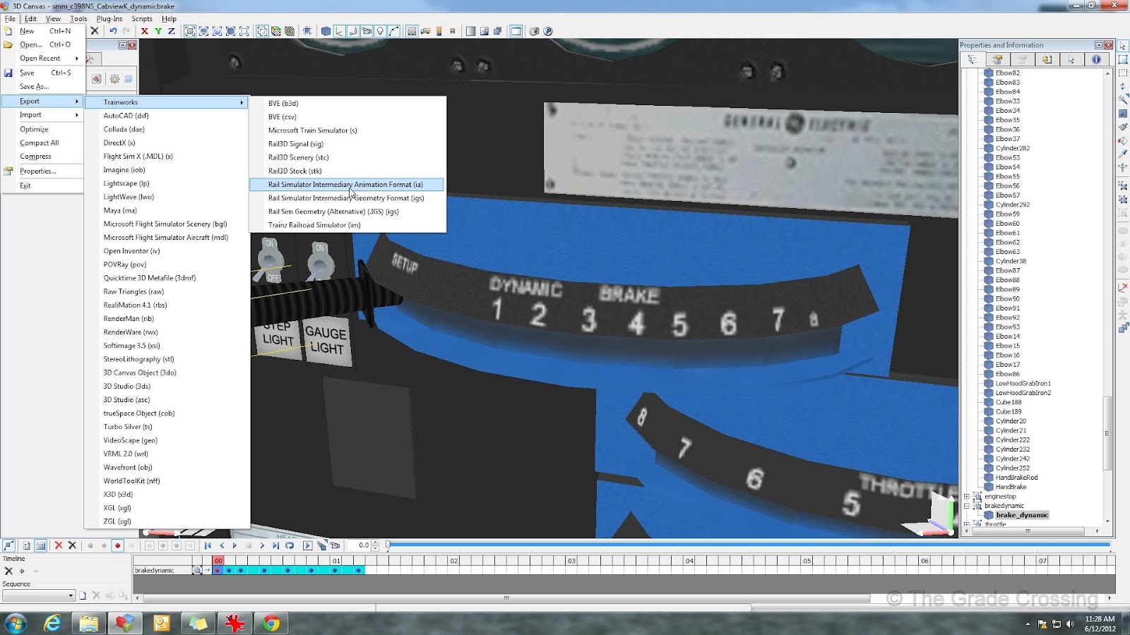
| 344. You only have to animate your part one way; the game will return the part to it's starting position. After you are finished with your animation, click on the part to be animated, then click the Main Menu, select "File", "Export", "Trainworks", and then "Rail Simulator Intermediary Animation Format (ia)". You will be prompted to switch to Modeling Mode and Continue. Select Yes.
|
|
| 345. Save your animation according to the part it represents on your locomotive.
|
|
| 346. Follow the same procedure for each part that you wish to animate for your locomotive. Next i'll do the horn, which on this locomotive model is a pull lever.
|
|
| 347. The dynamic brake requires a bit more movement and all sixteen Keyframes. Don't worry about the gaps between key frames; the game will smooth out the movement.
|
|
| You can check the backside of your DB handle to see the actual path of the animation.
|
|
| Save your animation as before.
|
|
| 348. Animate your throttle and reverser from their starting positions. Save and export them separately.
|
|
349. The speedometer is a seven point animation. In order to "calibrate" the speedometer so that it will show the same speed as the HUD in the game, you may need to do a trial-and-error procedure once you get the locomotive in the game. You should calibrate it to the highest speed of your locomotive. If when you reach that speed your speedo needle is lagging behind, you may need to increase how far the needle in the animation moves from zero. If the speedo needle is ahead of the top speed, you will need to decrease how far the need moves from zero.
Once you have the top speed of the HUD and the Speedo Needle matched, you can further refine the Calibration by moving the numbers around in the speedometer texture so that they match the markers at 10, 20, 30 mph, and so forth.
(Revised 2012-0704)
|
|
| 350. The ammeter and air system dials present a special problem. They are canted at an angle to the main X/Y axis, so moving them is going to require some thinking. To move them over and keep them lined up as they are supposed to be, you are going to move them in small increments and alternate between moving the X axis ( drag the red gizmo, lower right of the screen) and the Z axis ( drag the blue gizmo, lower right of the screen ). It takes some getting used to.
|
|
| 351. For the dual air gauges, I moved and exported each needle separately and in small increments. I gave the needle a blue key frame at each 10 psi increment. This may not be necessary for smooth movement in the game, but because of the awkward angle I had to animate these at, it made it easier to get smooth movement.
|
|


Laurens.Elgersma@gmail.com
ReplyDelete